
| Home | Energy Physics | Nuclear Power | Electricity | Climate Change | Lighting Control | Contacts | Links |
|---|
NITRATE SALT LOOP:
This web page is devoted to the atmospheric pressure nitrate salt loops that convey heat from the NaK-nitrate salt heat exchangers located in the heat exchange galleries to the steam generators located in the remote turbine halls. The nitrate salt mix consisting of 60 weight % NaNO3 and 40 weight % KNO3 is known as "solar salt". The NaNO3 has a melting point of 581 K = 308 C. The KNO3 has a melting point of 607 K = 334 C. Together they form a low melting point eutectic. This eutectic is claimed to be usable for heat transport from about 260 degrees C up to 560 degrees C. It is liquid at lower temperatures down to 223 degrees C but it becomes viscous and potentially abrasive crystals form.. In the FNR power plant the salt's normal operating temperature range should be from 280 degrees C up to 500 degrees C. There is no intent to use this salt near the low end of its temperature range where due to high viscosity it might not adequately drain down or near the high end of its temperature range where it might chemically decompose.
At temperatures less than 260 degrees C the nitrate salt is drained down to a dump tank and heat transfer in or out of NaK is accomplished using a synthetic organic heat transfer fluid.
At the FNR nitrate salt loop operating temperatures the density of solar salt is about:
Rho =1.8 g / cm^3
and its specific heat is about:
Cp = 1.1 J / g-deg C.
Thus [Cp Rho] for nitrate salt is at least 6X the comparable [Cp Rho] value for NaK. This relationship allows use of 8 inch diameter pipes for nitrate salt to convey the same heat flux is is conveyed by NaK in 18 inch diameter pipes.
SPACE ALLOCATION:
At the edge of each heat exchange gallery is 1.5 m dedicated to each heat transfer circuit. The NaK-nitrate salt heat exchangers are staggered so that one heat exchanger fits between two adjacent 18 inch diameter pipes.
All of these calculations assume use of 90 degree pipe elbows with diameter D, inside radius = (D / 2), outside radius = (3 D / 2).
The equipment is supported by a cross beam for each heat transfer loop which runs under the centerline of each induction pump.
The induction pump length is limited to:
8 m - (insulated elbow length) - (2 flange connection allowances)
= 315 inch - (27 inch + 6 inc) - 12 inch
= 270 inch.
In practise that will likely be limited to 240 inch due to practical induction pump material issues.
Thus the 8 inch nitrate salt discharge and return pipes go down on either side of the 18 inch inlet elbow to the induction pump.
More likely a heat exchanger diameter limitation on the cross wise axis.
TEMPERATURE AND POWER CONTROL:
The nitrate salt discharge temperature from the NaK/nitrate salt heat exchanger is controlled at 440 degrees C by varying the speed of the NaK induction pump. Note that the thermal load never drops below 10% of full power. Hence the steam input temperature seen by the turbogenerator is nearly constant independent of load.
The nitrate salt is circulated using a variable speed pump which is operated to control the generated electric power.
An important issue with the nitrate salt is maintenance of a nearly constant nitrate salt supply temperature to the steam generators. The issue is that steam turbines are sensitve to changes in steam temperature. If the steam temperature rises quickly the turbine blades generally warm up faster than the turbine casing. Under these circumstances, due to relative thermal expansion, the turbine blades can impact the turbine casing, causing major turbine damage. The solution is to ensure that the nitrate salt supply temperature remains constant irrespective of changes in the nitrate salt flow rate that might be forced by corresponding changes in the NaK flow rate which set the reactor power. Typically the nitrate salt flow rate must be proportional to the NaK flow rate.
Thus in normal system operation the temperature profile in the heat transport system remains nearly constant independent of reactor thermal power.
FAILURE TOLERANCE:
The nitrate salt loops are sized and vented for safe tolerance of either ruptures of NaK-nitrate salt heat exchanger tubes or failures of steam generator tubes. There are also various material considerations relating to the compatibility of the nitrate salt mix and stainless steel and the compatibility of stainless steel with the organic heat transfer fluid used to heat or cool the FNR as required to enable equipment service.
Each nitrate salt loop operates with both ends vented to the atmosphere via tall vents. The nitrate salt loop pipes slope monotonically toward the nitrate salt drain down tanks located below the steam generators. The nitrate salt drain down tanks have organic heat transfer fluid heating coils for remelting the nitrate salt when necessary.
GASKETED PIPE MECHANICAL JOINTS:
A major constraint on assembly and service of liquid sodium cooled FNRS
is the gasketed flanged pipe joints necesssary for connecting and disconnecting NaK pipes in the field. The issue is that at 450 degrees C the NaK and nitrate salt are chemically aggressive on elastomeric gaskets. The whole issue of the optimum gasket material needs more study. A major potential problem is NaK leaks and consequent small fires at the NaK pipe gaskets in the heat exchange galleries.
REFERENCE PAPERS:
Nitrate Salt Properties
Corrosion of iron stainless steels in molten nitrate salt
Corrosion Resistance of Stainless Steels During Thermal Cycling in Alkali Nitrate Molten Salts
MOLTEN NITRATE SALT HEAT TRANSPORT:
The molten nitrate salt acts as a thermal fluid and transports heat from each NaK-nitrate salt heat exchanger under the interior lane, to a turbine hall which contains the corresponding steam generator. The nitrate salt return pipe comes back under the interior lane to the NaK-nitrate salt heat exchanger. The nitrate salt pipes must all monotonically slope toward the nitrate salt dump tanks, which must be at a lower elevation than both the NaK-nitrate salt heat exchanger and the steam generator to enable gravity drainage of nitrate salt.
The two end high points in each nitrate salt circuit are vented to the atmosphere via 16 inch diameter vents which are sufficiently tall to allow for the change in nitrate salt level due to the nitrate salt pump pressure differential.
Thus, when the air pressure over the nitrate salt dump tanks is released, provided that the nitrate salt is molten, all the nitrate salt in the nitrate salt loop drains into the nitrate salt dump tanks.
The nitrate salt circulation pump is magnetically coupled to avoid hot nitrate salt leakage along the pump shaft. To give this pump positive suction head the pump is located at a nitrate salt loop low point close to the discharge from the nitrate salt dump tanks. However, this pump requires air pressure over the nitrate salt dump tanks to provide the initial required pump suction head.
In the event of a NaK-salt heat exchanger tube failure the higher pressure NaK will enter the molten nitrtate salt circuit where it will rapidly chemically react with the molten salt producing nitrogen. The nitrogen will displace salt in the NaK-nitrate salt heat exchanger shell, and will force molten nitrate salt to discharge out the adjacent nitrate salt vent.
As the NaK loses pressure and its level decreases the air pressure over the nitrate salt dump tank is released causing the remaining salt in the NaK-nitrate salt heat exchanger to drain down into the nitrate salt dump tank(s). The nitrogen producing chemical reaction will continue as long as there is any NaK above the NaK-nitrate salt heat exchanger tube rupture. Thus the nitrate salt vent diameter and the various pressure ratings must be sufficient to safely manage this rapid nitrogen production and discharge.
As soon as the nitrate salt level drops below the bottom of the NaK-nitrate salt heat exchanger the NaK should be dumped to the NaK dump tanks.
An important ongoing operating issue is maintenance of sufficient thermal flux and molten nitrate salt flow to prevent the molten nitrate salt from freezing in the external pipes or in the steam generator.
The steam pressure in the steam generator shell must be kept sufficiently high to keep the steam generator water temperature and hence the molten nitrate salt return temperature well above the nitrate salt melting point. The molten nitrate salt supply upper temperature is limited by the primary sodium temperature. The molten nitrate salt return temperature must kept above 320 degrees C to prevent it freezing in the pipe and to prevent NaOH in the secondary sodium depositing on heat exchange surfaces. This objective is accomplished by modulating the induction pump flow rate to keep the nitrate salt return temperature at about 330 degrees C_____.
If the molten salt temperature falls below its melting point there will be no heat transport away from the NaK-salt heat exchanger. When it is necessary to cool the primary sodium below 300 degrees C for service or other purposes heat should be removed from the NaK using heat transfer fluid cooling instead of salt cooling. The nitrate salt is drained to its dump tank(s). Then heat transfer fluid is used to fill one of the intermediate cooling circuits. The steam generator turbine bypass valve is openned. Then evaporation of water in the steam generator will extract heat from the primary sodium pool. Additional water must be added as this water evaporates.
HEAT TRANSPORT OVERVIEW:
In a liquid sodium cooled Fast Neutron Reactor (FNR), for safety purposes, each system that transports heat out of the primary sodium pool has both an isolated NaK loop and an isolated nitrate salt loop between each intermediate heat exchange bundle immersed in the primary liquid sodium and its corresponding steam generator. There is an induction pump in each NaK return pipe from a NaK-nitrate salt heat exchanger to its corresponding intermediate heat exchange bundle. There is a magnetically coupled molten nitrate salt pump in the return pipe from the nitrate salt dump tanks to the NaK-nitrate salt heat exchanger. The nitrate salt dump tanks have heat transfer fluid heaters to remelt the nitrate salt when necessary.
There is an electric heater used to raise the heat transfer fluid temperature to supply the heat for melting the primary sodium.
The nitrate salt level in the nitrate salt dump tanks is controlled by the air pressure over the nitrate salt dump tanks. This gauge air pressure varies from zero when these dump tanks are full of salt about 0.2 MPa when these dump tanks are almost empty.
The nitrate salt circuit is vented to tha atmosphere at both ends to ensure that the nitrate salt pressure is always lower than the water/steam pressure in the steam generator and is always lower than the NaK pressure at the NaK-nitrate salt heat exchanger. The NaK pressure is maintained by the argon pressure in the NaK dump tank.
In the event that the NaK level or NaK pressure decreases the compressed air over the nitrate salt dump tanks is released which allows the molten nitrate salt to drain out of the NaK-nitrate salt heat exchanger and related pipes and to flow down into the nitrate salt dump tank. This arrangement prevents molten nitrate salt entering the NaK loop via a NaK-nitrate salt heat exchanger tube rupture.
Should a NaK-nitrate salt heat exchanger tube rupture occur at a time when the nitrate salt circuit contains water nitrate salt drain down is again used to prevent water entering the NaK loop.
|
|
NITRATE SALT VOLUME:
Eight inch diameter Schedule 40S pipes:
Inside diameter = 8.625 inch - 2(0.322 inch) = 7.981 inch = 0.2027 m
Cross section = Pi (0.2027 m / 2)^2 = 0.03227 m^2
Length = 101.8 m_________
Volume = 0.03227 m^2 (101.8 m) = 3.29 m^3
Twelve inch diameter Schedule 40 S pipe:
Inside diameter = 12.000 inch = 0.3048 m
Cross section = Pi (0.3048 m / 2)^2 = 0.07296 m^2
Length = 6.9 m
Volume = 6.9 m (.07296 m^2) = 0.5034 m^3
0.5 m diameter pipe
Cross section = Pi (0.25 m )^2 = 0.196 m^2
Length = 4.9 m
Volume = 0.9604 m^3
Shell side of the NaK-nitrate Salt heat exchanger:
Pi (Shell ID / 2)^2(6 m) - (Number of tubes) Pi (7 inch /16)^2 (6 m)
= 4.5840 m^3
The steam generator contains a nitrate salt volume of: 1.394 m^3
Heat transfer circuit nitrate salt volume
= 3.29 m^3 + 0.5034 m^3 + 0.9604 m^3 + 4.5840 m^3 + 1.394 m^3
= 10.73 m^3
This estimate is known to be short on the vents and extended pipes. Hence we need a third dump tank.
Corresponding available nitrate salt dump tank volume:
3 dump tanks, each 48 inch OD X 5 m tall nitrate salt column
Volume = 3 X Pi (45.5 inch / 2)^2 X (.0254 m / inch)^2 X 5 m
= 15.73 m^3
The electricity output from a FNR should be controlled by modulating the nitrate salt flow rate.
There is a significant transportation time delay between a change in nitrate salt flow rate and the corresponding change in rate of steam production.
Hence during a system startup the NPP uses an autosynchronizing method to match the generator frequency and phase to the line frequency and phase with no load to connect the electricity generator to the grid.
Each steam generator has a local control loop that adjusts the steam pressure regulating valve (PRV) to attempt to maintain a steam pressure of 10 MPa in the steam generator which has the effect of setting the steam generator water temperature at 310 degrees C. This temperature must be maintained to prevent the nitrate salt freezing.
If there is a sudden loss of electrical load on the generator the turbine RPM will and a steam turbine bypass valve must rapidly open to prevent dangerous turbine over speed. Even if the nitrate salt flow rate is immediately reduced on loss of system electrical load there is a significant amount of thermal energy contained in circulating hot nitrate salt that must be safely dissipated to prevent turbine damage due to over speed. That dissipation is achieved by bypassing steam to the condenser.
Each steam generator is fitted with a rupture disc that will vent steam to the atmosphere if the pressure in the steam generator exceeds the maximum safe working pressure for the steam generator shell.
Each steam generator has a local control loop which maintains the desired water level in the steam generator by controlling the rate of high pressure condensate water injection. In the event of a sudden pressure rise in the nitrate salt, indicating a steam generator tube leak, the injection water flow is cut off and the steam generator drain valve is openned.
Up to six steam generators have their PRV steam discharge ports feeding a common turbine and share a common turbogenerator condenser. Hence the system can potentially accommodate a wide range of commercial steam turbo-generators varing from 6 MWe to about 38 MWe.
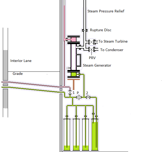
DIAGRAM:
A diagram showing the connection configuration of one of six identical steam generators in each turbine hall is shown below. One FNR can support up to eight identical turbine halls.

FNR STEAM GENERATOR DESCRIPTION:
A FNR steam generator is in essence a vertical tube in shell heat exchanger with water and steam flowing upward outside the tubes but inside the shell and molten salt flowing downward inside the tubes. A FNR steam generator and its support equipment must be designed so that when a steam generator heat exchange tube fails that failure does not create a dangerous situation. Note that the water/steam pressure is always much greater than the nitrate salt pressure. When one heat transport circuit is shut down the remaining parallel connected heat transport loops should continue safe operation.
In this design high pressure water/steam leaking through a tube failure into low pressure nitrate salt expels that salt via an adjacent atmospheric salt vent. Another atmospheric salt vent at the Heat Exchange Gallery limits the pressure drop along the salt pipes and hence prevents salt hammer of the heat exchange tubes of the NaK-nitrate salt heat exchanger and steam generator. That hammer effect could be due to water leaking into the salt loop via a steam generator tube failure or due to NaK leaking into the salt loop via a NaK-salt heat exchanger tube rupture.
The nitrate salt flows downward inside the steam generator heat exchange tubes and the water/steam occupies the space outside the heat exchange tubes but inside the steam generator shell. This space is rated for a maximum working pressure of 12 MPa. Much of the water inside the shell is in the form of steam with a relatively low density.
Due to the latent heat of vaporization of water the downward molten salt mass flow rate in the steam generator is much higher than the upward water/steam mass flow rate.
The injection water is normally at a high pressure (10 MPa) while the molten salt is normally at a very low pressure (~ 0.2 MPa).
The molten salt is hotest in the upper manifold of the steam generator and flows downwards through the heat exchange tubes. The water is coolest near the bottom of the steam generator shell and expands almost straight upwards.
During normal operation a steam pressure regulating valve (PRV) connected in line between the steam generator steam discharge pipe and the corresponding turbine keeps the steam pressure inside the shell at about 10 MPa. This pressure in combination with the properties of water keeps the super heated liquid water inside the steam generator shell bottom at 310 degrees C.
CONDENSATE AND EMERGENCY WATER INJECTION:
It is necessary to control each steam generator injection water pump to control the water level in the corresponding steam generator. Note that the time constant of this control loop should be small compared to the rate of change of the reactor power which controls the NaK flow rate. It is important to not reduce the reactor power too quickly to prevent flooding of the steam generator tubes above the sleeves. Such flooding could potentially lead to the nitrate salt freezing in the steam generator tubes.
A key safety issue on loss of station power is to continue removal of fission product decay heat. That requires maintaining the water level in at least some of the steam generators and maintaining the circulated nitrate salt temperature to prevent the salt freezing. If the nitrate salt is in danger of freezing heat transport loops that use heat transport fluid must continue the heat removal.
On loss of station power the steam generator pressure should be maintained to maintain the salt temperature so that it can circulate to remove fission product decay heat. When city water is available the reserve water tanks should automatically refill.
THERMAL PERFORMANCE:
At full thermal load the resulting temperature distribution is as follows:
Steam generator steam discharge temperature = 400 C
Steam generator water temperature = 310 C
Steam generator salt inlet temperature = 440 C
Steam generator salt discharge temperature = 320 C
NaK inlet temperature = 450 C
NaK discharge temperature = 330 C
Primary sodim discharge temperature = 460 C
Primary sodium return temperature = 340 C
The primary sodium return temperature mixes with the primary sodium bulk pool temperature to give a fuel bundle inlet temperature of about 410 C.
TUBE FAILURE PROTECTION AND MITIGATION:
In a continuously operating energy generation system sooner or later there will be a steam generator heat exchange tube failure. Such a failure will potentially allow high pressure water to flow through the rupture and into the molten salt.
There must be molten salt pressure relief vents to the atmosphere at the steam generator and at the sodium-salt heat exchanger ends of the molten salt circuit of sufficient size to prevent molten salt circuit equipment damage.
An important issue in FNR steam generator design is preventing a water leak from a steam generator tube rupture from causing a serious accident. When high pressure water and steam jets into the low pressure hot molten salt the molten salt is propelled at a high speed toward the atmospheric vents.
FNR STEAM GENERATOR PRESSURE ISSUES:
In normal operation the steam generator shell side contains high pressure (10 MPa) water/steam. However, the shell should be hydraulic pressure tested to at least 18.0 MPa to safely manage 12 MPa maximum possible steam working pressure transients that might occur.
The steam generator tubes contain molten salt normally at a pressure of about 0.2 MPa.
There are molten salt pressure and temperature sensors. An unanticipated transient increase in molten salt pressure or level indicates either a steam generator tube failure or possibly a NaK-nitrate salt heat exchanger tube rupture.
The nitrate salt circuit, if working pressure rated for 2 MPa, can safely manage a high pressure water/steam tube rupture by expelling salt out its atmospheric vents.
On the occurrance of a steam generator heat exchange tube failure high pressure water and steam will jet through the failure and into the nitrate salt. There will be a rapid pressure rise in the nitrate salt mitigated by the atmospheric vents at both ends of the nitrate salt loop. The rate of the pressure rise is limited by:
a) Use of narrow heat exchange pressure tubes which limit the incoming steam / water flow rate;
b) Use of salt loop vents that are open to the atmosphere.
d) Stopping of the injection water pump. There are two series connected pump control relays activated by independent high pressure sensors for certainty in stopping high pressure water injection into the steam generator;
e) Openning the steam generator drain valve;
f) Opening of the steam vent valve bypasses steam to the condenser.
g) Stopping the NaK induction pump and draining both the nitrate salt and the NaK to their respective dump tanks prevents further heating of the salt by the reactor and thus limits the total amount of transient heat that must be dissipated.
h) Complete closing of the steam pressure regulating valve (PRV) prevents reverse steam flow through the pressure regulating valve.
SHUTDOWN SEQUENCE:
The system must be designed to:
1) Remain structurally safe in the presence of fluid hammer;
2) Prevent a dangerous pressure transient reaching the connected NaK-nitrate salt heat exchanger;
3) In the event of tube damage to the NaK-nitrate salt heat exchanger the system must
rapidly and safely vent the nitrogen gas (and possibly hydrogen if there is any water in the nitrate salt loop) to prevent nitrate salt or water entering the NaK loop and causing yet more damage.
4) Open a steam generator drain valve and use the residual steam pressure to rapidly expel liquid water from the steam generator shell into the drain;
5) Turn off the injection water pump to stop the injection water flow;
6) Release high pressure steam from the steam generator shell to the condenser to stop water / steam jetting into the salt from both sides of the tube rupture;
7) Force the steam pressure regulating valve fully closed to prevent steam from other steam generators back flowing backwards through the steam pressure regulating valve;
8) Turn off the NaK induction pump to prevent further heat input from the reactor;
9) Drain the nitrate salt to its dump tanks;
10) Safely isolate components for cleanup and repair.
RESTART SEQUENCE:
11) Confirm correct NaK level and presence of argon cover gas at 0.5 MPa;
before restarting the NaK induction pump at a low flow.
12) Use electric heaters in dump tanks to bring the nitrate salt up to temperature
13) Start the NaK induction pump at low flow;
14) Apply air pressure over the nitrate salt dump tanks to refill the salt loop;
15) Start the nitrate salt circulation pump;
16) Close the steam generator drain valve;
17) Enable the steam generator injection water pump;
18) Use the steam bypass valve to synch the generator to the line;
19) Close the generator main contactor;
20) Increase the nitrate salt flow to achieve the desired generator power.
There must be fully redundant pressure relief safety devices (rupture disks) to ensure steam generator pressure safety because failure of the motorized valves to work as contemplated could otherwise have serious consequences. In addition to steam pressure sensors there must be water level sensor and a molten salt level sensor at the steam generator to to control the injection water pump and to sense a transient increase in molten salt pressure caused by a steam generator heat exchange tube leak.
HEAT EXCHANGE TUBE FAILURES AND RUPTURES:
The worst FNR nightmare is an event which causes water to flow into the primary sodium pool. In normal reactor operation such an event requires three simultaneous tube failures in the steam generator, the NaK-nitrate salt heat exchanger and in the intermediate heat exchanger. During cool down for equipment service such an event requires simultaneous failures of tubes in the NaK-nitrate salt heat exchanger and in the intermediate heat exchanger.
To prevent this type of accident the nitrate salt/water circuit is immeidately automatically drined if the NaK pressure falls below a threshold well above the maximum nitrate salt/thermal fluid pressure.
The purpose of the system safety design is to prevent such an accident ever happening. Even if the tubes in both the steam generator and the NaK-nitraate salt heat exchanger simulataniously rupture the higher pressure in the NaK circuit should prevent such an accident occuring.
The nitrate salt loop pressure relief pipes must be large enough (0.5 m diameter) to ensure that nitrogen (and perhaps hydrogen) can be vented as fast as it can be generated, which in the case of effects of a NaK-nitrate salt heat exchanger tube rupture and/or a steam generator tube failure are limited by the maximum possible NaK flow rate through the throats of the ruptured NaK-nitrate salt heat exchange tubes.
The worst case consequence of any potential steam generator or NaK-nitrate salt heat exchanger tube rupture are physically limited by the use of 48 independent heat transfer circuits.
Note that the liquid water flow through a steam generator heat exchange tube failure and into the nitrate salt will stop when the steam generator is drained. However, the steam flow into both sides of the tube failure will continue until all the steam in the steam generator shell is vented. The over pressure in the nitrate salt should cause the steam bypass valve to the condenser to discharge steam from the steam generator shell as fast as possible so that steam does not continue to flow into the nitrate salt.
The steam pressure regulating valve (PRV) needs to be fully closed to prevent steam back flow from other parallel connected steam generators.
EXTENDED NITRATE SALT PIPING:
Outside the heat exchange galleries the 8.625 inch OD nitrate salt pipes angle monotoniclly downwards towards the remote steam generators and their accompanying dump tanks. These pipes go under the interior lane between the heat exchange galleries and the turbogenerator halls. Each nitrate salt pipe feeds a dedicated steam generator.
RUPTURE FLOWS:
Assume a heat exchange tube size of 0.500 inche OD, 0.065 inch wall thickness. The resultind ID is:
0.500 inch - 2 (0.065 inch) = 0.370 inch
= 0.370 inch X 0.0254 m / inch = .0009398 m
Tube cross sectional area
= Pi (.0009398 m / 2)^2
= 6.9368 X 10^-5 m^2
In a tube:
Flow power = force X velocity
= (pressure X area X velocity)
Flow power = kinetic energy / unit time
= (mass / sec) X (velocity)^2 / 2
= (density X area X velocity X (velocity)^2 / 2
Equating the two expressions for flow power gives:
pressure = density X velocity^2 / 2
or
Velocity = [2 X pressure / density]^0.5
or
volumetric flow rate = area X [2 X pressure / density]^0.5
or
mass flow rate = density X area X [2 X pressure / density]^0.5
= area X [2 X pressure X density]^0.5
Hence the maximum flow rate of super heated water through a single heat exchange tube is:
= 6.9368 X 10^-5 m^2 X [ 2 X 11.25 X 10^6 Pa X 1000 kg / m^3]^0.5
= 6.9368 X 10^-5 m^2 X [2 X 11.25 X 10^6 kg m /s^2 m^2 X 1000 kg / m^3]^0.5
= 6.9368 X 10^-5 m^2 X 15 X 10^4 kg / s m^2
= 10.4052 Kg / s
The corresponding rate of production of hydrogen gas is:
(10.4052 kg / s) / 16 = 0.6503 kg / s
At 0 degrees C, 1 atmosphere (.101 MPa), one mole (2 gm) of hydrogen gas occupies 22.4 lit. At 430 deg C one mole of hydrogen occupies [(430 + 273 ) / 273] X 22.4 lit = 57.68 lit. At 2.0 MPa and 430 degrees C 2 gm of hydrogen gas occupies:
57.68 lit X (0.101 MPa / 2.0 MPa) = 2.913 lit
Thus the enclosed volume required to safely absorb the released hydrogen at 2.0 MPa is:
0.6503 kg / s X 1000 g / kg X 2.913 lit / 2 gm X 1 m^3 / 1000 lit
= 0.6503 X 2.913 / 2 m^3 / s = 0.947 m^3 / s
Assume that the vent pipe is 16.000 inch OD schedule 80 (0.843 inch wall) so the ID is 14.314 inch. Then the volume of that pipe is:
Pi (14.314 inch / 2 X .0254 m / inch)^2 X L
= 0.10382 m^2 L
Hence if L = 10 m the vent pipe will reach its maximum safe hydrogen pressure of 2.0 MPa in about:
(0.10382 m^2 X 10 m) / (0.947 m^3 / s)
= 1.096 s
Thus on the occurrence of a single tube rupture the 16 inch ball check must move from full closed to full open in about 1.1 seconds.
Another important constraint is how fast it is possible to continuously vent 2.0 MPa of hydrogen through a 16 inch OD vent pipe. Assume that the pipe inside cross sectional area is 0.10382 m^2 as calculated above.
As indicated above the hydrogen gas density at 2 MPa is:
2 gm / 2.913 lit = 2 X 10^-3 kg / 2.913 X 10^-3 m^3 = 0.6866 kg / m^3
Recall that:
mass flow rate = area X [2 X pressure X density]^0.5
Thus at 2.0 MPa the maximum hydrogen venting rate is:
mass flow rate = 0.10382 m^2 X [2 X 2.0 X 10^6 Pa X 0.6866 kg / m^3]^0.5
= 0.10382 m^2 X [2 X 2.0 X 10^6 kg m / s^2 m^2 X 0.6866 kg / m^3]^0.5
= 0.10382 X 1.657 X 10^3 kg / s
= 172 kg / s
Thus under these circumstances the maximum tolerable number of simultaneous steam generator tube ruptures is:
(172 kg / s) / (0.6503 kg / s-tube) = 264 tubes
However, the intermediate heat exchangers and the steam generator shell side must also be rated for a 2.0 MPa working pressure at their operating temperature. Hence if the hydraulic pressure testing of the steam generator shell is done at room temperature, the intermediate heat exchanger tube side and the steam generator shell must be subject to a hydraulic pressure test at:
2.0 MPa X 1.5 = 3.0 MPa.
Hence for the NaK we can use schedule 40S pipe and fittings. However, we need a schedule 160 steam generator shell due to the large diameter branch pipes connecting to the shell.
On the occurance of a heat exchange tube failure in a steam generator the 1st object is to reduce the liquid water level in the lower shell as fast as possible so that only steam feeds the rupture. The second object is to reduce the steam pressure in the upper shell as fast as possible to limit the mass of steam ultimately injected into the nitrate salt via the tube rupture.
This web page last updated February 26, 2023
| Home | Energy Physics | Nuclear Power | Electricity | Climate Change | Lighting Control | Contacts | Links |
|---|