| Home | Lighting Control | Nuclear Power | Contacts | Links |
|---|
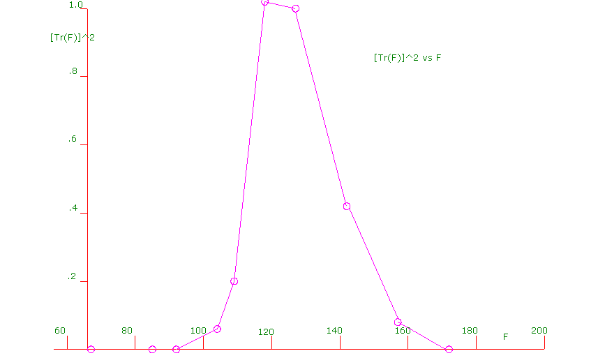
| F(kHz)--- | Tr(F)--- | [Tr(F)]^2--- | Area |
|---|---|---|---|
| 67 | .01274 | .000162 | 0 |
| 85 | .01380 | .000190 | 0 |
| 92 | .06684 | .004468 | 0 |
| 104 | .2540 | .064516 | .414 |
| 109 | .4466 | .199452 | .660 |
| 118 | 1.0116 | 1.023335 | 5.502 |
| 127 | 1.0 | 1.0 | 9.105 |
| 142 | .6456 | .416799 | 10.626 |
| 157 | .2917 | .085089 | 3.764 |
| 172 | .0490 | .002401 | .656 |
The Integral{[Tm(F)]^2}dF is simply the area under the above curve.
Integral{[Tr(F)]^2}dF = 30.727 kHz
This measured bandpass is almost exactly Systel's stated design objective.
Recall that the RMS noise voltage Vnr seen by the PLC receiver input is given by:
[Vnr]^2=(Vb)^2Integral{[Tr(F)]^2}dF
or
[Vnr]^2= (Vb^2)(30.727 kHz)
or
Vnr= Vb(5.543) (kHz)^0.5
For a typical value of Vb = 4.04 mV / (kHz)^0.5,
Vnr = 4.04 X 5.543 = 22.4 mV
This web page last updated September 20, 2005
| Home | Lighting Control | Nuclear Power | Contacts | Links |
|---|