| Home | Lighting Control | Nuclear Power | Contacts | Links |
|---|
A Premium Circuit Filter should be used if the broad band noise level at 127 kHz exceeds 100 mV rms / (30 kHz)^0.5 or if other FCC approved PLC equipment is or may be connected to the same power distribution transformer secondary and the branch lighting circuit length is less than 200 m.
Premium Circuit Filters have the disadvantages that they cost about twice as much as Standard Circuit Filters and they absorb power at their filter resonant frequency (~7 kHz).
A Premium Circuit Filter increases the range and reliability of the PLC communications for lighting control, prevents PLC signals on one branch lighting circuit interfering with PLC signals on another branch lighting circuit, prevents the PLC lighting control signals from interfering with other PLC systems, and prevents other FCC approved PLC systems interfering with the PLC Lighting Control System.
A Premium Circuit Filter functions by preventing PLC band signals from passing through it in either direction. It minimizes lighting control PLC signals that are impressed upon the circuit breaker panel electrical bus; it prevents other PLC signals and electrical noise propagating from the circuit breaker panel electrical buses to branch lighting circuits; and it prevents a low circuit breaker panel electrical bus impedance from attenuating the lighting control PLC signals on the branch lighting circuits.
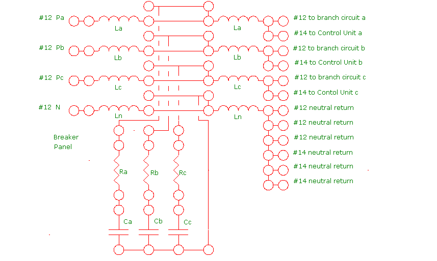
Pictorial diagram for assembly of a 3 phase Premium Circuit Filter.
In the Premium Circuit Filter the size of the components is primarily limited by component cost considerations. The inductor value choice for 120 volt lighting circuits is:
La = Lb = Lc = Ln = 50 uH.
The inductors must be rated for 15A or 20A depending on the circuit breaker size. These inductors should have self resonant frequencies that are far above the operating frequency. The experimental prototype inductors had self resonant frequencies of 3.4 MHz.
The capacitor value choice for 120 volt lighting circuits is:
Ca = Cb = Cc = 10 uF. This capacitance is readily available.
The capacitors must be rated for continuous use with AC. A 600 to 1000 volt AC continuous rating is suggested, although a 250 volt AC continuous rating may be sufficient for a 120 volt lighting circuit.
Dry film capacitors are used to avoid the use of oil filled capacitors. The issue is that over time the oil might deteriorate and become a fire hazard. The capacitors must be engineered such that their effective series resistance and distributed inductance are negligible below 500 kHz.
section to be inserted here?????
The maximum 127 kHz band noise coupling from the circuit breaker panel electrical bus to the branch lighting circuit occurs when the branch lighting circuit is short and contains only a few ballasts, so that its impedance is relatively high. Let Zb be the impedance of the branch lighting circuit.
At 127 kHz, for L= 50 uH the term 2WL has a value of:
2WL = 2 X 6.28 X 1.27 X 10^5 X .5 X 10^-4 = 79.75 ohms
Consider a branch lighting circuit that is relatively short and that consists of three connected two lamp ballasts:
Information provided by Systel indicates that the impedance of one two lamp ballast at 127 kHz is about 483 ohms inductive, so three ballasts in parallel will give an impedance of about 161 ohms inductive. This impedance makes:
Zb = 2(2jWL). Hence, the transfer function simplifies to:
T = (R - (j/WC))/[3(R-(j/WC)+jWL)-(R-(j/WC))]
or
T = (R - (j/WC))/[2R-2(j/WC)+3jWL]
At high frequencies T is inversely proportional to frequency. However, this transfer function has a low self resonant frequency Wr given by:
(2/WrC) = 3WrL
or
Wr^2 = 2/(3LC)
or
Fr = (1 / 6.28)[2 /(3LC)]^0.5
For L = 50 uH, C = 10 uF:
Fr = 5.8 kHz
This filter resonant frequency is well removed from the operating frequency.
At the filter resonant frequency the transfer function simplifies to:
T = (R - (j/WrC))/[2R]
In order to prevent the PLC receiver clipping it is necessary to limit the maximum magnitude of the Premium Circuit Filter output voltage. To achieve this objective limit |T| to unity. Then:
1^2 = (R^2 + (1 / WrC)^2) / 4R^2
or
3R^2 = (1/(WrC)^2)
or
R = (1/WrC)(1/3)^0.5
Thus for L = 50 uH and C = 10 uF, R is given by:
R = 1.58 ohms
Use a 1.5 ohm 10 watt resistor which is a standard value.
Recall that the transfer function for Zb = 4jWL is:
T = (R - (j/WC))/[2R-2(j/WC)+3jWL]
Evaluate this transfer function at 127 kHz:
At 127 kHz:
1/WC = 1 / (6.28 X 1.27 X 10^5 X 10 X 10^-6) = .125
3WL = 3 X 6.28 X 1.27 X 10^5 X 50 X 10^-6 = 119.63
so
T = (1.5 - .125j)/[3 -.250j+119.63j]
= (1.5 - .125j)/[3 +119.38j]
|T| ~ 1.5 / 119.38 = .01256
The interfering signal is divided by (1 / .01256) = 79.6 which exceed the design target set out in the section titled Interference Issues.
Hence, for a load consisting of 3 two lamp ballasts the Premium Circuit Filter reduces the noise voltage coupled from the circuit breaker panel electrical bus to the branch lighting circuit by a factor of .01256. For design purposes it is convenient to impose the requirement that there are always at least three two lamp ballasts connected to a branch lighting circuit.
Note that if there is a 3.5 volt rms 127 kHz interfering signal on the electrical bus this interfering signal is reduced to:
3500 mV X .01256 = 44 mV.
As the number of connected ballasts increases, Zb decreases causing the coupled noise level to decrease. Hence the coupled noise level is always less than 50 mV.
Assume the worst case which is a branch lighting circuit that is connected to the same phase of a lighting circuit breaker panel as is a high impedance load that is sensitive to the PLC signal. Assume the worst case that all the other connected electrical loads are off. Then Zb = infinity and the transfer function from the lighting circuit to the circuit breaker panel electrical bus is given by:
T = (R - (j/WC))/[2(R-(j/WC)+jWL)-(R-(j/WC))]
=(R - (j/WC))/[R-j/WC+jWL]
At 127 kHz, with L= 50 uH and C= 10 uF, T is given by:
T = (1.5 - .125j) / (1.5 - .125j + 39.877j)
= (1.5 - .125j) / (1.5 + 39.752j)
|T| ~ 1.5 / 39.752 = .0377
Assume that the maximum lighting control PLC signal is 2.5 V rms. Then the maximum possible noise impressed on the breaker panel bus by the PLC signal becomes:
2500 mV X .0377 = 94.3 mV.
This voltage drops rapidly as the breaker panel bus impedance decreases.
This web page last updated September 20, 2005
| Home | Lighting Control | Nuclear Power | Contacts | Links |
|---|