 SINGLE TURBO GENERATOR HALL LAYOUT.
| Home | Energy Physics | Nuclear Power | Electricity | Climate Change | Lighting Control | Contacts | Links |
|---|
NUCLEAR ELECTRICITY:
A Fast Neutron Reactor (FNR) produces heat at up to about 460 degrees C. The most practical way to convert that heat into electricity is by using the heat to produce high pressure steam. For safety the FNR is isolated from the water/steam system by NaK, nitrate salt and heat transport fluid (HTF) loops. Due to the characteristics of the heat transport fluids the optimum steam pressure is about 10 MPa.
Multiple independent heat transport loops are used to provide a high degree of reliability and safety. Selected heat transport loops can be shut down without significantly impacting either electricity or heat production/removal.
The steam expands through steam turbines which in turn drive line synchronous generators that produce 60 Hz 3 Phase electric power.
The turbine discharge low pressure steam is condensed by a heat sink consisting of circulated low temperature district heating water. The low grade heat in this water is used together with water source heat pumps in buildings to provide 60 degree C water for space and domestic hot water heating. This district heating arrangement is economic in urban areas of circumpolar countries where concentrations of high rise residential buildings as are common.
When the low grade heat has no commercial value it is dumped to the atmosphere via distributed cooling towers.
The main benefits of this system are a four fold electric energy consumption reduction for comfort heating as compared to electric resistance heating and a four fold reduction in the winter electricity demand peak.
There are secondary benefits relating to avoiding need for new electricity transmission corridors into existing urban centers.
This web page addresses the equipment layout in the FNR turbo generator halls.
MODULAR EQUIPMENT:
This web page addresses the equipment layout in the FNR turbo generator halls.
The equipment in the turbogenerator halls is modular. Every module is factory tested. The main modules having significant size and weight are:
Steam generators
Dump tanks
Nitrate salt pumps
Heat transfer fluid pumps
Steam pressure control and relief valves
Condenser
Turbogenerator frame
High pressure turbine
Low pressure turbine
Condenser
Feed water pump
Generator stator
Generator rotor
Generator main switch
Pump disconnects, pump starters, control and monitoring equipment
Heat sink valves
TURBOGENERATOR HALL LAYOUT:
There are two different possible equipment layouts. One layout is for a single 37.5 MWe turbo generator per hall which is fed steam by six parallel connected heat transport circuits. The other layout is for 2 X 18.75 MWe turbo generators where each turbogenerator is fed steam by three parallel connected heat transport circuits.
A possible advantage of the single 37.5 MWe equipment configuration is a smaller equipment capital cost on a dollars per MWe basis. Another advantage of the single 37.5 MWe turbogenerator configuration is that there is more turbogenerator hall space, which reduces pipe and equipment congestion.
An advantage of the 2 X 18.75 MWe equipment configuration is that the individual modules are smaller and lighter making their transport, installation and subsequent maintenance easier.
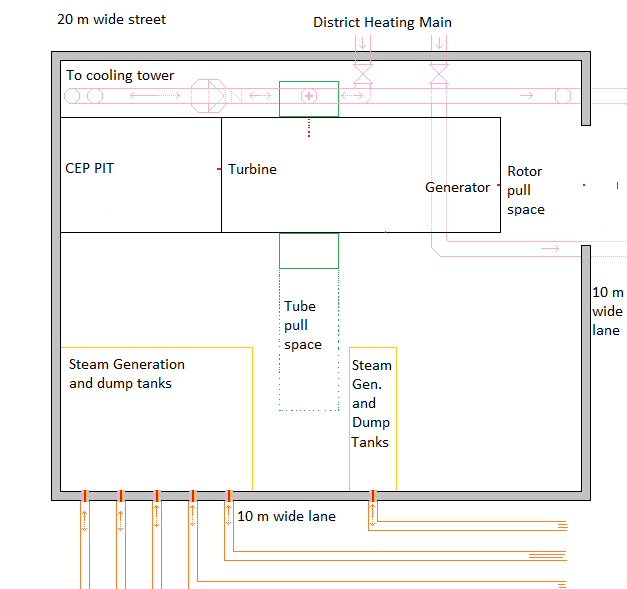
The approximate layout for a single 37.5 MWe unit is shown below. Note that the steam generators are concentrated in the lower left hand corner of this diagram. The steam main should run clockwise around the diagram following the adjacent wall as far a the CEP Pit.
SINGLE TURBO GENERATOR HALL LAYOUT.
The steam generator and dump tank configuration for each of the six heat transport circuits supplying steam to each turbogenerator hall is shown on the following diagram.
When there are two 18.75 MWe turbogenertors in the same turbo genertor hall the layout is as shown in the following diagram.
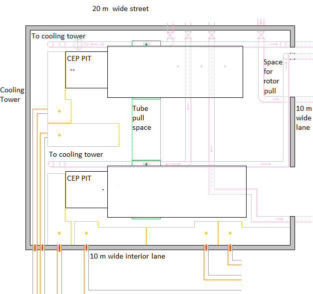 FNR DUAL TURBO GENERATOR HALL LAYOUT
where in this case the steam generators and the dump tanks serving the lower turbo generator are located along the bottom of the diagram and the steam generators and dump tanks serving the upper turbo generator are located on the left hand side of the diagram. Note that this equipment is spaced off the left hand wall by the width of two nitrate salt pipe loops, which reduce available space in the lower left hand corner of the diagram.
NOTES RELEVANT TO BOTH DIAGRAMS:
1)The right hand wall must contain a rollup commercial garage type door for each turbogenerator. These doors open onto the 10 m wide radial lane. At this time the 18.75 MWe unit is shown with a 5 m wide door and the 37.5 MWe unit is shown with a 6 m wide door. These door widths should be reviewed.
2) There are two levels of below grade district heating pipe shown in pink. This low temperature district heating system provides the heat sink for the turogenerator condensers. For the 18.75 MWe unit the pipe is 24 inch diameter. For the 37.5 MWe unit the pipe is 30 inch diameter. The pipe and condensers must be rated for a working pressure of 160 psi (about a 100 m head of water). They must be presure tested at 240 psi.
3) On the opposite side of the 10 m wide radial lane is a second turbogenerator hall which is almost a mirror image of the turbogenertor hall shown in the diagram. The district heating water flows from a buried 48 inch diameter return main, through the first turbogenerator hall, under the 10 m wide radial lane, through the second turbogenerator hall and then out to a 48 inch diameter district heating supply main.
4) Heat is supplied to each turbogenerator hall by 6 X 8 inch diameter buried pipes containing hot nitrate salt that enter the turbogenerator hall along the bottom of the diagram. Each heat transport circuit has a corresponding temperature regulated NaK-salt heat exchanger and a NaK-HTF heat exchanger located in a heat exchange galery in the nuclear island on the opposite side of the 10 m wide interior lane. On these diagrams the outside cover of the nitrate salt pipe insulation is 0.5 m diameter and is shown in orange. For drainage purposes these pipes must continuously slope downwards toward the dump tanks in the sub-basements of the turbogenerator halls.
5) At full load each nitrate salt loop and HTF loop pair should deliver about 21 MWt of heat.
6) Each turbogenerator hall has in integral X-Y gantry crane consisting of 26 m long rails and a 21.5 m long travelling bridge. A suitably rated hoist runs back and forth along this bridge. Note that in the case of the single 37.5 MWe generator, due to the greater unit weights, the gantry crane may need to be more robust than in the 2 X 18.75 MWe case.
7) The gantry crane rails will need dedicated support pillars. Various equipment items may need to be slightly shifted to accommodate the gantry crane rail support pillars.
8) It is intended that the gantry crane be used to position and/or remove any of the heavy equipment items in the turbo generator hall with minimal necessity for moving obstructing items.
9) Note that the steam and electrical lines should be routed so as to not obstruct the loaded gantry crane travel.
10) Each turbo generator hall has multiple levels. The upper level, slightly above grade, contains the turbogenerators and electrical gear. The bottom level contains the condenser and dump tanks. Above the dump tanks are the steam generators.
11) The below grade district heating pipes are mainly at the level of the bottom of the turbogenerator condensers. Note that the outside district heating mains are also at this lower level. Heat sink water pipes from the top of the condensers are below the turbogenerator slabs and return to the bottom of condenser level before exiting the turbogenerator hall. Each such water pipe has an isolation valve at its point of connection to the external district heating loop.
12) The walk ways have removable floor grills to allow access to lower level equipment.
13) Each module is delivered to the site on a flat deck truck. The truck backs down one of the 10 m wide radial lanes until its load is opposite a lane facing door to the turbogenerator hall. The load is lifted off the truck deck with a chain hoist supported by an ovehead beam that span the width of the lane.
The truck is driven away. The load is lowered onto a low slung wheeled cart. The cart is pulled into the rotor pull area of the turbogenertor hall. The load is picked up by the X-Y gantry crane of the turbogenerqtor hall and is moved to its desired position.
14) Once the module center of mass is in the rotor pull area the module can be picked up by the internal gantry crane, rotated and moved horizontally and vertically within the turbo generator hall.
15) The module will be lifted off the truck with the module long axis parallel to the radial lane axis. During the aforementioned shifting the module may need to be rotated 90 degrees about its vertical axis to fit through the rollup door. If the module's maximum horizontal diagonal dimension exceeds the 10 m lane width, to enable a 90 degree rotation about the module's vertical axis the doors of the turbogenerator halls that open onto the lane must be sufficiently wide and suitably positioned so as to increase the effective lane width at the point of rotation.
16) The diagonal distance between opposite door edges must be greater than the longest diagonal distance on the condenser. The radial lane is 10 m wide and in the 37.5 MWe case the condenser is almost 10 m long. If the condenser is less than 4 m wide and the opposite rollup doors are both at least 4 m wide performing this rotation in the radial lane should be possible. Once the condenser is fully inside the turbogenerator hall another 90 degree rotation is required to get it into its final position. Removing the condenser at a later date may require moving a significant amount of obstructing equipment.
17) For now the rollup door widths are shown as 5 m and 6 m.
18) At this time the turbogenerator hall gantry crane hoist and bridge load ratings are tentatively 20 tonnes. We need to determine with certainty what is the largest single load that the gantry crane must manage in the 18.75 MWe case and in the 37.5 MWe case.
19) The modules must all be accurately dimensioned and pretested such that everything fits together and immediately operates as specified.
20) The FNR Turbo Generator Hall diagram shows that the turbogenerator hall's inside length is 26.0 m and the hall's inside width is 21.5 m. The 18.75 MWe turbo generators should have a 4.7 m end clearance for generator rotor insertion and removal. This end clearance area is also used for receipt and removal of other heavy items.
21) For the 37.5 MWe generator the rotor pull clearance extends through the rollup door and out over the radial lane.
22) There is also a space requirement for nearby electrical equipment which must not obstruct the gantry crane load travel. For the dual turbogenerator arrangement this electrical gear can go in the space between the two turbo generators but snug against each turbo generator so as to maintain sufficient corridor space for moving steam generators and dump tanks parallel to the turbogenerator axis.
23) For the single turbogenerator arrangement the electrical gear can be located in the lower right hand corner of the room.
24) In the dual turbogenerator arrangement there is a region about 2.5 m wide where the insulation of the steam generators is within 0.1 m of the edge of the lower turbogenerator mounting pad. Does this close proximity cause a potential problem. For example, does lack of clearance violate any elctrical code requirements for 1 m of front clearance?
25) The available real estate dimensions force the axis of the turbines to be parallel to the axis of the inside lane. If a turbine was to blow up there are 0.5 m of reinforced concrete between the turbine and the public street, there are 1.5 m of reinforced concrete between the turbine and potential serious consequential equipment damage and there are 2.5 m of reinforced concrete between the turbine and a potential major public emergency. Regulatory authorities will demand certainty as to the effectiveness of those amounts of concrete in containing a turbine blowup.
26) Whether the turbo generator hall contains 1 X 37.5 MWe or 2 X 18.75 MWe affects the configuration of buried pipe under the adjacent street and under the radial and inside lanes, so the decision as to which turbogenerator configuration to adopt is of major import.
27) Further, the gantry crane used for a 2 X 18.75 MWe turbo generator hall may not be compatible with a 1 X 37.5 MWe turbogenerator hall. In adddition to different unit weights there are different hall depths.
This web page last updated May 23, 2023
| Home | Energy Physics | Nuclear Power | Electricity | Climate Change | Lighting Control | Contacts | Links |
|---|