INTRODUCTION:
The FNR Skirt is a 6 m wide band of metal that wraps snugly around the perimeter of the FNR fuel assembly. The FNR Skirt mechanically contains the fuel assembly and reduces the peripheral neutron flux.
Most of the information on this web page is related to matters that determine the exact dimensions of the FNR Skirt and its components.
FNR PLAN VIEW:
The following diagram shows the plan view of the fuel bundle array.
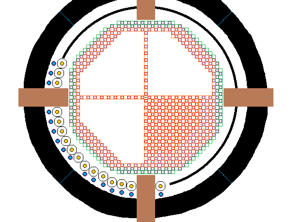
A FNR consists of central active fuel bundles surrounded by passive fuel bundles and cooling fuel bundles which in turn are surrounded by the FNR Skirt with its gadolinium layer and then a ~ 1.7 m wide liquid sodium guard band. Within the guard band are the 48 intermediate heat exchangers along the path shown as a solid black ring. The primary sodium pool walls are 2 m thick and are filled with fire brick. In the above diagram only one quadrant of fuel bundles is fully detailed.
The above diagram is to approximate scale. The active movable square fuel bundles are shown in red. The passive fixed square fuel bundles are shown in purple. The cooling bundles are shown in green. For structural stability the diagonal fuel bundle assembly faces are composed of fixed octagonal fuel bundles, except at 8 clipped corners. A shaped 6 m high steel skirt covered on one side with sheet gadolinium is wrapped around the perimeter of the assembly of fuel bundles at the same elevation as the fixed fuel bundles. The skirt consists of eight straight sections. Each straight section is fastened at each end to a 45 degree corner post. There are eight such corner posts.
FNR FUEL BUNDLE DIMENSIONS:
The external dimensions of the tubed portion of a movable fuel bundle including shroud thickness, fabrication tolerance allowance, thermal expansion allowance and swelling allowance are:
[19 X (5 / 8)] inches wide X [19 X (5 / 8)] inches long X 6 m tall. At the inner face of the shroud the tubed portion of the fuel bundle dimensions are:
[17 X (5 / 8)] inches wide X [17 X (5 / 8)] inches long X 6 m tall.
FUEL BUNDLE SWELLING ALLOWANCE:
Each movable fuel tube bundle has a (5 / 8) inch thick provision all the way around for the shroud thickness, fabrication tolerance allowance, thermal expansion allowance and swelling allowance. From the web page titled: FNR Fuel Bundle the shroud plate thickness is:
3 / 16 inch.
Hence, even with perfect movable fuel bundle fabrication, the maximum fuel bundle swelling allowance is:
{[2(5 / 8) inch - 2(3 / 16) inch] / 17 inch} X 100% = 5.14%
The significance of this permitted swelling fraction is that when the fuel bundle swelling in the core zone reaches 5% the fuel bundle must be reprocessed, regardless of its contained Pu or fission product fractions.
FIXED FUEL BUNDLE DIMENSIONS:
Neglecting the corner clips the maximum diagonal width of a fixed fuel bundle is given by:
23 X (5 / 8) inch X (2)^0.5 = 20.329 inch. Hence the fuel bundle transfer airlock should be made from 24 inch diameter pipe.
The external dimensions of a fixed fuel bundle including shroud thickness, tolerance allowance and thermal expansion allowance are:
[23 X (5 / 8)] inches face to face X [23 X (5 / 8)] inches face to face X 6 m tall. The octagon allowances are formed by clipping off 2 fuel bundles off each corner of a 23 X (5 / 8) inch X 23 X (5 / 8) inch square. Each fixed fuel bundle shroud contains:
[(21 X 21) - 4(6)] = 417 fuel tube positions.
However, an additional 33 fuel tube positions are lost to diagonal fuel bundle reinforcement members leaving a net of:
417 -33 = 384 fuel tubes per fixed fuel bundle.
In order to achieve both good liquid sodium natural circulation, which requires fuel tubes on a square grid, and good horizontal mechanical stability a mixture of smaller movable and larger fixed fuel bundles is used. The maximum face to face size allocation for the fixed fuel bundles is set at:
23 X (5 / 8) inch = 14.375 inches
by transportation weight constraints. The movable fuel bundles are made as large as practical:
19 X (5 / 8) inch = 11.875 inches face to face
with respect to the fixed bundles to achieve acceptable fuel bundle assembly structural strength and acceptable modulation of average core zone fissile fuel concentration. These dimensions result in a linear center to center spacing of:
[14.375 inch + 11.875 inch = 26.25 inch
= 26.25 inch X .0254 m / inch = 0.66675 m.
This dimension is close enough to (2 / 3) m to permit a scale plan view diagram in m rather than inches.
The above diagram was prepared using a scale of:
14 squares = (2 / 3) m
On the above diagram the ratio of the small square size to the larger square size is not exactly correct but it is close enough for diagramatic purposes.
ASSEMBLY OF FUEL BUNDLES:
The fuel bundle geometry starts as a 45 X 45 square. The straight horizontal and vertical faces are each 21 bundles long. Hence each of the cut off corners of an isosoles triangle is:
(45 - 21) / 2 = 12
bundle positions to a side. Hence the number of movable fuel bundle positions in each cut off corner is:
12 + 10 + 8 + 6 + 4 + 2 = 42
and the number of fixed fuel bundle positions in each cut off corner is:
11 + 9 + 7 + 5 + 3 + 1 = 36
so the number of cut off corner fuel bundle positions is:
42 + 36 = 78= 78.
The result is an octagon. In addition two fixed and one movable fuel bundle are clipped of each of 8 octagon corners to avoid clashing with neighbouring intermediate heat exchange bundles.
To minimize the liquid sodium requirement the assembly of fuel bundles is chosen to be close to a regular octagon so that it will fit snugly within a circular liquid sodium tank wall. Before octagon corner clipping the octagon straight faces consist of 11 octagonal fuel bundles separated by 10 square fuel bundles. The length of a straight side measured between the centers of the end bundles is:
10 X 42 X (5 / 8) inch = 262.5 inch.
Measured from the ends of these fuel bundles the straight face length is:
262.5 inch + 23(5 / 8) inch = 276.875 inch
The octagon angled faces each consist of 13 corner connected octagonal fuel bundles. Straight and diagonal face fuel bundles are shared at corners.
Measured along a diagonal through octagonal fuel bundles, the center to center distance between adjacent octagonal fuel bundles is:
(2^0.5) X [21 X (5 / 8) inch]
= 18.561 inch
Measured from octagonal fuel bundle center to octagonal fuel bundle center the length of a diagonal face is:
12 X 18.561 inch
= 222.738 inch
which is less than would be the case for an ideal regular octagon.
The fuel bundles are a subset of a theoretial array 45 bundles X 45 bundles. There is a fixed bundle at each corner of the theoretical array and there is a fixed bundle at the center of the array.
Measured from fixed fuel bundle center to fixed fuel bundle center the horizontal face to horizontal face distance of the
entire assembly of fuel bundles is:
[44] X [(21 X (5 /8) inch] = 577.5 inch
Measured from the outside edges of the octagonal fuel bundles the fuel bundle assembly the horizontal face to horizontal face distance is:
577.5 inch + [23 X (5 /8) inch] = 591.875 inch
= 591.875 inch X .0254 m / inch
= 15.034 m
GUARD BAND:
The intermediate heat exchange bundles are located at an elevation above the top of the fuel tubes, so that primary sodium guard band extends under the intermediate heat exchange bundles. The reactor primary sodium pool is 20 m inside diameter which provides a neutron absorbing guard band greater than 1.7 m thick around the perimeter of the fuel bundle assembly. The primary sodium pool liner and the heat exchange bundle supporting steel columns are further protected by sheet gadolinium in the FNR Skirt. The heat exchange bundles are protected from neutrons originating in the core fuel via a very long diagonal path through the fuel blanket.
FUEL BUNDLE ASSEMBLY FACE TO FACE OUTSIDE DIMENSION CHECK:
[23 X 23 X (5 / 8) inch] + [22 X 19 X (5 / 8)inch]
= [(23 X 23) + (22 X 19)] X 5 / 8 inch
= (529 + 418) X (5 / 8) inch
= 539.375 inches
= 591.875 inch X 0.0254 m / inch
= 15.034 m
The corresponding radius is:
15.034 m / 2 = 7.517 m
FUEL BUNDLE ASSEMBLY MAXIMUM RADIUS BEFORE OCTAGON CORNER CLIPPING:
The maximum fuel bundle assembly radius is:
= {[(face to face diameter) / 2]^2 + [(face length) / 2]^2}^0.5
= {[(591.875 inch) / 2]^2 + [(276.875 inch) / 2]^2}^0.5
= {87,579.00 inch^2 + 19,164.94 inch^2}^0.5
= 326.717 inch
= 326.717 inch X .0254 m / inch = 8.2986 m
Thus, before octagon corner clipping the maximum available ring width for heat exchangers plus relative thermal expansion allowance is:
10.00 m - 8.30 m = 1.70 m
With octagon corner clipping this allowance increases to about 1.8 m.
INTERMEDIATE HEAT EXCHANGER RING WIDTH:
Around the perimeter of the fuel bundle array there must be ring of sufficient width for the intermediate heat exchangers. There is space for 48 heat exchangers in a single ring plus 4 X 2 m allowances for airlock related equipment.
Each heat exchange bundle manifold is 38 inches in diameter as set by perimeter pressure flange requirements. The outer manifold edge of the ring of heat exchangers is 0.6 m from the pool wall. Hence the ring of heat exchangers are on a circle with a radius of:
10 m - 0.6 m - 19 inch(0.0254 m / inch)
= 9.4 m - 0.426 m
= 8.974 m
~ 9.0 m
On this circle the ring of heat exchanges are spaced center to center at:
2 Pi (8.974 m) / 56 = 1.00688 m intervals
= 39.64 inch intervals.
Hence the minimum required primary sodium pool radial width taken up by the intermediate heat exchangers is:
0.6 m + 38 inch
= 0.6 m + .9652 m inch
= 1.565 m
PRIMARY SODIUM POOL DIAMETER:
Recall that the maximum fuel bundle assembly maximum radius is:
= [20 m - 2(1.8 m)] / 2 = 8.20 m
Thus the minimum required primary liquid sodium pool inside radius is:
8.20 m + 1.565 m
= 9.765 m
~ 10.0 m
so with reasonable construction tolerances the required primary sodium pool inside diameter is 20.00 m
FUEL ASSEMBLY SKIRT:
The fuel assembly skirt is a wide band of sheet metal that surrounds and confines the assembly of fuel bundles. This skirt provides the assembly of fuel bundles collective horizontal stability and has a gadolinium layer for neutron absorption, which layer protects the primary liquid sodium pool liner and exposed parts of the intermediate heat exchange bundles from long term neutron absorption. This skirt is 6 m high and normally is at the same level as the fixed fuel bundles. This skirt is supported by 7.5 m tall posts that fasten to the top of the open steel lattice. The radial bottom reinforcement of the skirt posts is limited to 2.0 m.
Primary liquid sodium coolant can easily circulate both above and underneath this skirt.
The circumferential length of this skirt is about:
4 X (276.875 inch + 222.738 inch) = 1998.452 inch
= 1998.452 inch X 0.0254 m / inch = 50.76 m
Hence the skirt surface area on one side is:
6 m X 50.76 m = 304.564 m^2>
The skirt is supported by 8 corner posts, each 7.5 m tall, which in turn are supported by the 1.5 m high open steel lattice.
Each of 4 skirt faces consists of three plates, each 2 m wide X ~ 5.657 m long. Each of the other 4 skirt faces consists of 3 plates, each 2 m wide X ~7.033 m long. Each plate runs between two adjacent corner posts. Thus all the skirt components will fit through an equipment transfer airlock.
Note that to extract an individual fuel bundle from the assembly of fuel bundles it is necessary to raise the fuel bundle 7.5 m to clear the top of the fuel assembly skirt.
EQUIPMENT TRANSFER AIRLOCK REQUIREMENTS IMPOSED BY SKIRT:<
In order to allow passage of FNR Skirt components the equipment transfer airlocks have to have an inside length greater than 7.5 m and an inside height greater than 2.0 m.
This web page last updated
February 12, 2022.