| Home | Energy Physics | Nuclear Power | Electricity | Climate Change | Lighting Control | Contacts | Links |
|---|
INTRODUCTION:
Elsewhere on this website Fast Neutron Reactors (FNRs) have been identified as the primary source of energy for meeting mankind's future energy needs. This web page focuses on FNR siting criteria.
ELEVATION OF THE SODIUM POOL:
The single most important issue in FNR siting is sufficient elevation of the liquid sodium pool with respect to nearby rivers and large bodies of water.
The sodium pool of a 1000 MWt FNR typically contains almost 4000 tonnes of liquid sodium at up to 500 degrees C, which if flooded by water will create a major disaster. Hence, safe containment of the sodium and its isolation from water are paramount.
Occasionally nature causes earthquakes, which if they occur under a large body of water, can cause a tsunami. A tsunami wave can cause major water damage. The following video shows some of the water damage caused by an earthquake triggered tsunami hitting a low elevation town in Japan. The only certain protection against tsunami damage is sufficient elevation of the FNR nuclear island.
A liquid sodium cooled Fast Neutron Reactor (FNR) must be sited sufficiently above nearby large nearby bodies of water to ensure that even under worst case conditions the flood water level will never reach the upper rim of a FNR's liquid sodium pool, thus ensuring that there will never be any direct contact between the liquid sodium and the flood water. This sodium pool elevation issue takes precedence over all other FNR siting considerations.
Generally speaking, FNRs should not be installed near water level at ocean or lake front locations that might be subject to tsunamis or earthquake or flood induced level rise and should not be installed on the flood plane of a river or downstream from a natural or constructed dam that might burst some time in the future causing an uncontrolled flood.
A good location for a FNR nuclear island is on a plateau at the top of a high solid granite cliff overlooking a major water body. Then high pressure steam pipes can be run from the nuclear island at the top of the cliff to turbogenertor barns located near water level. That site configuration provides both sufficient elevation for sodium pool security and abundant water for absorbing waste heat from thermal electricity generation.
Outside the sodium pool enclosure there should be a grade contour which drains surface water away from the nuclear island. Without any pumping the local water table at the nuclear island should normally be at least 19 m below grade. However, sufficient stored water should be available at the NPP for interim emergency dissipation of fission product decay heat by evaporation of the stored water.
THe ideal location for a FNR is on a hard rock hill. The bottom of the FNR foundation should be sufficiently above the bottom of the hill to ensure gravity water drainage from the bottom of the FNR foundation. There must be truck road access to grade level at the nuclear island.
Ideally the hill extends further upwards from the nuclear island to allow gravity supply of stored emergency cooling water. Further advantages of such a hill are that it will help to conceal the NPP and it will make low level airborne attack difficult. The hill above the nuclear island should not be composed of loose material that could develop into a mud slide that threatens the nuclear island.
FNR SITE BEDROCK ISSUES:
Ideally for both safety and long term structural stability the sodium pool of an FNR should be installed in a cavity cut out of a granite mountain. However, such ideal FNR sites are seldom available in urban locations.
The FNR enclosure should either be set on a natural hill or should be built into a synthetic earth hill that provide both water exclusion and protection against impact by external objects such as aircraft. If used the earth embankments should either have surface paving or sodding to ensure drainage of rain water off the surface or should be of coarse gravel so as to prevent the embankment material becoming saturated with water.
GROUND LOAD BEARING CAPACITY:
The sodium pool, the open steel lattice, the fuel bundles and the intermediate heat exchange byndles present a load of about 8000 tonnes distributed over a sodium poolbottom area of about 300 m^2, corresponding to an average load of about 26 tonnes / m^2. After allowing for the foundation, the underlying bedrock must be able to continuously support 30 tonnes / m^2. The corresponding downward pressure is:
30,000 kg / m^2 X 9.8 m/ s^2 = 294,000 N / m^2
An ideal near water front site for a FNR is a dense igneous rock plateau that drops off quickly to a lake, large river or ocean heat sink with a long term high water mark more than 17 m below the plateau grade. The water body depth should be sufficient to prevent silt and/or sand being sucked into the cooling water makeup system. The sodium pool elevation above the water level must be sufficient that no natural geophysical event can ever lead to water threatening the primary sodium pool. Channels or tunnels can be cut into the bedrock surrounding the FNR to ensure positive gravity drainage. There should be radial gravity drains that will drain rain water out from under the reactor. The plateau should provide sufficient area (154 m X 154 m) for a FNR NPP.
The drainage required to ensure long term below grade dryness of any hill where a FNR is installed will likely have an adverse effect on any nearby shallow fresh water wells.
Shale is a fine-grained, clastic sedimentary rock composed of mud that is a mix of flakes of clay minerals and tiny fragments (silt-sized particles) of other minerals, especially quartz and calcite. The ratio of clay to other minerals is variable. The shale that typically exists about 7 m below grade under Toronto has a maximum load bearing capacity of about 5000 kPa. Shale is not as good as granite but it is adequate for FNR support if there is a suitable baseplate.
A FNR located in steep granite mountains might have a natural draft cooling tower concealed within a granite core mountain. This cooling tower concealment methodology might be applied in mountainous regions of British Columbia or Labrador but it is impractical in most of Ontario.
Note that the elevation of a FNR nuclear islnd with respect to a nearby large body of water is much higher than the usual elevation of a CANDU reactor that uses direct lake or sea water cooling.
BASEPLATE:
The baseplate is usually a concrete disc about 54 m diameter and 5 m to 8 m thick that supports all the components of the nuclear island, that keeps these components in the same relative positions during an earthquake and that prevents penetration by ground water.
A major issue in FNR siting is the required baseplate thickness and reinforcement. If the FNR's foundation is a solid chunk of crackfree high silica granite (igneous rock) in principle that granite can act as the FNR baseplate. However, often such a single piece granite foundation is not available and a concrete baseplate is required.
If the surrounding ground becomes saturated with water, in effect the nuclear island acts as a concrete boat 52 m in diameter with a bottom 20 m to 25 m below grade. This concrete boat displaces as much as:
Pi (26 m)^2 (25 m) = 53,093 tonnes of water. The bottom of this boat is subject to a uniform upward hydraulic pressure of:
1000 kg / m^3 (25 m)(9.8 m / s^2) = 245,000 Pa
= 245 kPa
However, the downward force on this boat bottom is in large measure due to the weight of the structural walls and the loads that they support, including the steam generators, induction pumps, heat exchange galleries and the dome roof. These downward forces are concentrated near the outer edge of the baseplate. This configuration leads to very large shear forces in the baseplate near the bottom of the structural concrete walls. This shear force concentration is opposed by the tensile strength of the concrete in the bottom half of the baseplate. However, unreinforced concrete is very weak in tension.
The compressive strength of concrete is typically about 30 MPa but the tensile strength of unreinforced concrete is only about 3 MPa.
The tensile strength of reinforced concrete is limited by the strength of its reinforcement. Hence the base plate must be quite thick and its bottom half must be heavily reinforced to provide the required tensile strength. Further, the concrete must be protected against long term water penetration. Typically the required base plate thickness is in the range 5 m to 8 m. The outer surface of the base plate and the nuclear island sidewalls should be protected by a thick layer of tar.
Ideally the concrete should be "Roman Concrete", not Portland cement. Roman concrete contains an excess of quick lime which gives it crack self-healing properties not available from portland cement. When first mixed Roman concrete liberates more heat than portland cement, which heat must be carefully managed.
STEAM PIPES:
The steam pipes that run from the steam generators to the turbogenerators are about 40 m long and must be geometrically configured to allow pipe thermal expansion and contraction. These 10 MPa steam pipes run through tunnels under the circular lane. The space inside these tunnels must be large enough to accommodate pipe thermal expansion and contraction.
REJECTION OF LOW GRADE HEAT:
After sufficient elevation relative to surrounding large bodies of water, the next important FNR siting criteria is ability to continuously dissipate 700 MWt of low grade heat. This heat is transferred to the atmosphere by formation of water vapor and then is emitted into outer space primarily by the photon emission accompanying repeated freezing and melting of water droplets in high altitude clouds.
However, at the reactor site heat is removed either by conduction/convection in a cooling tower or by conduction/convection through a buried district heating pipe network. That district heating pipe network in turn dissipates heat by some combination of:
a) Transferring heat to a district heating load by thermal conduction and water convection. The heat loads ultimately transfer the heat to the atmosphere, again primarily by thermal conduction.
b) Transferring heat by conduction/convection to a large body of open water such as a major river, a large lake or the ocean. That body of water then evaporates transfering the heat to other atmospheric gases. In that process the water condenses and falls as rain.
c) Transferring heat to a cooling tower. The cooling tower transfers sensible heat heat to the atmosphere. In essence the cooling tower is a fin-tube radiator with dampers for freeze protection and possibly a fan for improved heat transfer.. Due to circulated water head pressure constraints the cooling tower operates dry.
A common theme of all the heat sinking methodologies is that nuclear electricity generation cannot occur without a sufficient heat sink.
In summary, an essential requirement for economic siting of a nuclear power plant is a reliable heat sink. For a 1000 MWt FNR, this heat sink must be able to continuously absorb at least 700 MWt of heat under all weather conditions.
URBAN REACTOR COOLING:
Few people are eager to reside adjacent to a 50 m to 125 m tall cooling tower, unless that tower is at least partially architecturally concealed by another tall structure. To the extent possible, the cooling towers at uban sites should be concealed by other nearby tall buildings.
A practical alternative urban reactor cooling methodology is for every premises that uses district heat in the winter to have roof mounted fan-coil units that can dissipate a comparable amount of heat to the atmosphere in the summer. In these circumstances the cooling towers of an urban reactor only have to be sized to dependably dissipate fission product decay heat. The alternative to these rooftop fancoil units is up to 12 remote cooling towers per FNR.
An urban FNR should have four cooling towers, any two of which should be sufficient for safe removal of fission product decay heat.
If the surrounding land is flat the combination of the hill on which the FNR is installed and the adjacent cooling towers will be prominent on the horizon. Hence, to avoid problems with neighbours, it may be prudent at rural FNR sites for the party that owns the FNR to purchase adjacent property within a 0.5 km radius of the FNR.
URBAN ELECTRICITY AND HEATING BACKUP:
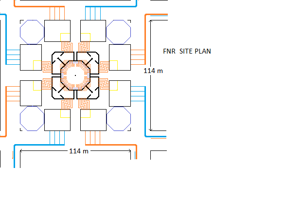
FNRs should be distributed over urban areas to provide district heating and to minimize the costs of AC power transmission corridors. In urban areas distributed FNRs should be located so that if an individual FNR is shut down for reactor maintenance the nearest neighbor FNRs can provide customers backup electricity. Backup heat must be available via pipeline supplied hydrogen or methane gas. Since each FNR and its support electrical facilities occupies a 114 m X 1114 m city block, long term planning is required for urban reactor siting. If 20 m wide perimeter roads do not already exist they must be provided, potentially requiring additional real property. The perimeter road requirement can potentially expand the minimum required FNR site size to 154 m X 154 m.
The recommended FNR urban site plan is shown below.
This site plan shows:
a) The central sodium pool, 20 m inside diameter with 2 m thick charcoal coloured side walls.
b) The 1 m thick concrete inner structural wall in gray.
c) The 1 m thick concrete outer structural wall in gray.
d) Eight 1 m thick major radial shear walls in gray.
e) The air locks in the spaces between adjacent major radial shear walls.
f) The turbogenerator barns in black.
g) The cooling towers in blue
h) Roof mounted transformers and electrical switchgear, on top of each turbogenertor barn, shown in pink.
i) A 7.5 m setback from the property line for above grade structures (red corner markers defining a 99 m X 99 m area).
j) The 114 m X 114 m one block area defined by black corner markers.
k) Perimeter roads each 20 m wide defined by black lines. The districht heating pipe network is buried under public roads. Orange indicates supply pipes, blue indicates return pipes.
l) A circular access lane between the nuclear island and the turbogenerator barns. The high presure steam and condensate injection pipes, with bends to accommodate thermal expansion, pass through tunnels under this lane.
m) Four radial lanes allow 18 wheel flat deck trucks to deliver and removal fuel bundles and intermediate heat exchanges to air locks.
This Nuclear Power Plant (NPP) site plan is consistent with the following asumptions:
a) The NPP is located in a city with a rectangular grid road network.
One mile is exactly 5280 feet. Hence each property block is marginally greater than 114 m to a side.
b) The municipality has a legislated above grade building setback of 7.5 m from the nearest public road allowance.
Hence all NPP above grade structures must fit within a square:
[114 m - 2(7.5 m)] X [114 m - 2(7.5 m)] = 99 m X 99 m
c) In plan view the above grade nuclear island footprint is a circle with a diameter of 52 m.
d) A hot fuel bundles must be safely and easily transferred between the nuclear island and a shielded container mounted on a flat deck truck.
Hence flat deck trucks must be able to back up to airlock external doors. The airlock bottom must be about 2 m above grade.
e) Under each airlock is a 2 m wide doorway to access the adjacent heat exchange galleries and a chainlift to the dump tanks.
f) The lane around the nuclear island must provide sufficient space for a crane truck, with a 15 m external turning radius, to deliver and remove construction materials, steam generators and induction pumps.
g) The entrance/exit laneways are 10 m wide.
h) The outside width of a turbogenerator barn is:
[99 m - 52 m - 2(10 m)] / 2 = 13.5 m
i) The turbogenerator barn walls are 0.5 m thick.
j) The inside width of a turbogenerator barn is:
13.5 m - 2(0.5 m) = 12.5 m
k) Hence for each turbogenerator the maximum width of the companion roof mounted electrical equipment is 12.5 m.
l) The base outside diameter of a cooling tower is:
35 (0.5 m) = 17.5 m
m) The outside length of a turbogenertor barn is:
[99 m - 2(17.5 m) - 10 m ] / 2 = 27.0 m
n) The inside length of a turbogenerator barn is:
27.0 m - 2(0.5 m) = 26.0 m
o) The district heating system isolation valves are located below grade under the 7.5 m setback.
p) Each of four district heating zones is served by two turbogenerators that are pipe connected under the 10 m wide entrance/exit lanes.
q)The turbogenerators are oriented with their generators close to the entrance/exit lanes.
r) The turbogenerator condensers are installed so that their tubes can be pulled by temporarily blocking the circular lane around the nuclear island.
s) The condensate pressure boost pumps consist of one low pressure pump for each turbogenerator, a preheater, followed by a high pressure pump for each of the associated six steam generators.
t) The condensate high pressure boost pumps located in the turbogenerator barns are modulated for water level control in the steam generators.
FNR DISTRICT HEATING NETWORKS:
Urban FNRs need to be about 25% oversized to have sufficient electrical capacity to serve adjacent zone customers when as many as two adjacent FNRs in a network are shut down for any reason. Geography permitting, in dense urban areas the FNRs should be installed on a grid that is approximately 1 mile (1.6 km) from one FNR to the next FNR to provide an average energy density of 2 MWe plus 4 MWt per square block, where a block is a parcel of land approximately 114 m X 114 m separated from adjacent blocks by 20 m wide road allowances. In less dense urban areas the optimum FNR to FNR spacing will be larger. The FNR grid spacing may also be affected by rapid changes in land elevation, by the presence of large commercial/industrial point loads and by the proximity of large bodies of water. Note that doubling the average FNR grid spacing quadruples the average network pipe length and reduces the average available energy per square block by a factor of four.
An important issue in designing a district heating system is the elevation of the various load heat exchangers with respect to the FNR. District heating systems involving distribution of heat via circulated water in buried pipes are subject to practical water pressure head constraints. Keeping the maximum hydraulic head pressure under 160 psig (1.1 MPa), as is required for use of common schedule 40 pipe, requires keeping the elevations of the load heat exchangers within 100 m of the elevation of the corresponding FNR condenser. Hence one FNR can economically serve a band of property with a mechanical room elevation range extending from about 100 m above the FNR's condenser to about 100 m below the FNR's condenser. Each FNR needs to be able to direct its excess thermal capacity to any combination of a high hydraulic head pressure zone, a low hydraulic head pressure zone or a steam heating zone, depending on the requirements of the heating zone being supported.
There is yet another important practical hydraulic piping network issue known as pump suction head. With respect to the heating loops that are lower in elevation than the FNR the main heating loop the circulation pumps should be located remotely near the lowest elevation part of the loop to ensure sufficient pump suction head to prvent pump cavitation under all circumstances.
District heat can also be distributed via steam as is presently done by Enwave, the operator of the Toronto District Heating System. Steam has advantages for large commercial and industrial customers but it usually needs to be converted into hot water for heat distribution to most smaller customers. Steam production also reduces the amount of electricity available from a NPP. The choice between steam and warm water on a radial heating line is dependent on the customer mix along that line. There are also serious safety considerations related to use of steam. Practical multi-residential district heating experience in Europe indicates a strong preference for super heated water (120 degrees C) rather than steam. When water source heat pumps are available it is more thermally efficient to deliver heat via circulation of warm water.
PROTECTION FROM ATTACK:
FNRs should be protected from malevolent attacks. To prevent a malevolent attack from above from causing serious consequences the nuclear island should be able to safely absorb the impact of a crashing aircraft. The roof structure should contain sufficient steel and kinetic energy absorbing material for this purpose.
In the event of a malevolent attack it is essential to rapidly remove heat from the liquid sodium to reduce its temperature to under 200 degrees C so that the sodium will not spontaneously burn in air, to exclude rain water and to maintain an aphyxiating sodium cover gas while extracting heat from the sodium to prevent a major sodium fire. Ideally spare temporary sheet metal roof material should be stored on the NPP site to be available for immediate deployment for rain water exclusion in the event of a roof rupture.
Once the sodium has cooled to near room temperature it can be isolated from air by flooding its surface with kerosene.
The hill on which a FNR is installed provides earth works at least 17 m thick around the FNR enclosure, which is enough to protect the FNR liquid sodium tank from an adjacent impact by a large aircraft travelling at close to the speed of sound. The concrete structures of the turbogenerator barns and the walls of the heat exchange galleries provide robust low angle aircraft impact protection. The threat that is most difficult to protect against is a vertical impact by a precision guided armour piercing bomb dropped from a high altitude and aimed at the dome roof over the sodium pool. Other than in a war, this is not a credible threat. Likewise, roof penetration by a large meteorite is not considered a credible threat.
SODIUM HANDLING:
There should be provision for nearby sodium storage with sufficient capacity to hold all the liquid sodium so as to permit future major maintenance/repairs to the FNR primary liquid sodium tank in the distant future. There must be a means of easily and rapidly transferring heat emitting fuel bundles from the liquid sodium pool to heat absorbing fuel bundle transport containers and vice versa.
The sodium will likely be delivered to the reactor site either in tanker trucks or as a solid in 55 US gallon steel drums with removeable covers. There may be as many as 24,000 such drums. These drums need to be stored on pallets in groups separated by aisles that act as fire breaks and provide access for fire suppression. A safe drum pallet size is 30 inches X 30 inches. Hence, exclusive of aisles, the single level drum storage space requirement is:
(30 inches X 30 inches) / drum X (.0254 m / inch)^2 X 24,000 drums = 13,935 m^2
The sodium filled drums will likely arrive by rail. Hence the drum storage site will likely need additional area for a rail siding and cargo transfer of:
1 Km X 50 m = .050 Km^2
ENERGY TRANSMISSION CORRIDORS:
Also important are the costs of electricity and heat transmission corridors from the NPP to the electricity and thermal loads. In an urban application the cost of the required energy transmission easements or corridors may dominate all other costs. Fully displacing fossil fuels will likely require at least a three fold increase in non-fossil electricity generation capacity and related electricity transmission capacity in Ontario. Hence the government of Ontario should identify and prohibit new development or redevelopment on land that will be required for distributed NPPs and for energy transmission corridors.
URBAN ISSUES:
In order to access the district heating load FNRs should be located within urban developments. However, within a major metropolis the land acquisition cost will increase many fold. That cost will be offset by the avoided cost of energy transmission from outside the city into the center of a city.
Also important is the proximity of the FNR sites to locations where the trained personnel required to assemble, operate and maintain the FNRs can comfortably live.
These real estate considerations point to the wisdom of Ontario Hydro during the 1970s in establishing major thermal electricity generation sites at Bruce, Darlington, Nanticoke, Wesleyville and Pickering and in laying out major electricity transmission corridors in Ontario. Today the whole issue of nuclear reactor siting and long term electricity and thermal energy transmission corridor planning needs to be revisited.
URBAN MARKET:
(a) To make economic sense a FNR must be able to reliably supply electricity and heat in urban markets in ratios that vary over time. To economically provide district heating FNRs must be sited in the middle of major cities which means that the FNRs must have no public safety issues that could impact persons outside the reactor site. Such FNRs must incorporate passive safety features that do not exist in current power reactors.
(b) Such FNRs must tolerate any credible malevolent attack or act of God without causing a significant public safety problem.
(c) The FNRs should be connected to their thermal and electrical loads without reliance on other electricity and natural gas utilities. The FNR owners must be able to easily obtain pipe and electrical easements under both public roads and private properties. The FNR owners must have the same legal status as present electricity and natural gas utilities with respect to obtaining easements.
(d) The NPP owners must be permitted to sell heat or electricity in any combination to end users without making payments to any other utility. For example the reactor owner must be able to sell electricity directly to major end users such as major building owners without paying a prohibitive distribution charge to an electricity utility. The technical issues of electricity load island formation, disconnection, automatic re-synchronization and re-connection to the electricity grid must be faced. There are related control and load sharing issues that the IESO thus far has not faced. An important issue is short circuit fault clearance in grid connected loads that are close to the distributed nuclear generation.
(e) Obtaining public utility status generally requires an act of a provincial legislature. Selling FNRs on a large scale will be all but impossible until a common industry body such as CNL takes on the related legislative challenges. It is necessary to draft enabling legislation that any Canadian provincial legislature can easily approve. The legislative model for district heating is likely Enwave in Toronto. However, realizing utility status for Enwave required a many year effort by an association of major hospitals and office building owners. Even so, Enwave does not sell electricity in competition with the Toronto Hydro Electricity System. The number of actual FNR installations will be negligible if each FNR project proponent must first successfully run a major political campaign.
(f) A related issue is the prevailing end user electricity rate structure. Much of the value of nuclear power as compared to intermittent wind and solar power lies in the dependability of nuclear electricity generation. In order for nuclear power to make financial sense to both suppliers and end users the electricity rate structure must properly reflect the value of a dependable kVA as compared to a kWhe. In the province of Ontario there are presently many retail electricity rate problems and there is almost no energy storage because the present retail electricity price plans charge too much per kWhe and too little per kWe or kVAe.
LEGAL COMPLICATIONS:
In Canada the present law related to attachments to a building makes it impractical for any party, other than the building owner, to finance the cost of the required changes to a building heating system necessary to connect it to a district heating system. The problem is that the first mortgage holder for a building has security primacy over all other creditors, including any creditor that finances changes to the building heating system. This issue is known as the law of attachments. In a building insolvency the lead mortgage holder usually sells the building to a third party. That third party has no legal obligation to the creditor that financed the heating system changes unless that creditor has a first charge on title. Fixing this problem requires a fundamental legislative change that places the security held by the party that financed the heating system changes ahead of the security held by the lead mortgage holder. This issue is a major legal obstacle to displacement of fossil fuels by non-fossil energy.
Fixing this problem is generally opposed by Canadian Banks and like financial institutions because it could potentially reduce their security. Governments must come to the realization that preventing climate change is more important than providing ultra high security to banks and like financial institutions that provide mortgages and lines of credit registered on property title.
CNSC REGULATION:
In 2018 the CNSC published a nuclear reactor siting document titled: Site Evaluation and Site Preparation. This document is presently very broad, includes by cross reference numerous other documents, infringes on matters of provincial and municipal jurisdiction and does not focus on the real requirements of urban siting of a nuclear power reactor. This document must be modified and simplified so as to meet the reasonable needs of urban planners, municipal utilities and major building developers.
The incorporation of other documents by cross reference must be eliminated. The scope of this document with respect to site research should be no more than the requirements for site approval of a 50 floor highrise building.
Above all, once a potential site has been selected, basic engineering suitability checks have been done and the scope of anticipated major on-site structures has been agreed upon, the jurisdiction of the CNSC with respect to the site selection must end. There must be no issue of future licence renewals or possible future changes in regulatory requirements. The CNSC agreement to the site selection and the composition of its major protective elements must be final.
There must be no possibility of project review under the Canadian Environmental Protection Act as is presently contemplated in the CNSC Site Evaluation and Site Preparation Documentation.
The sites for urban nuclear reactors will be determined first by basic engineering issues such as site dimensions, site elevation, site drainage, depth to bedrock and road access, secondly by existing and future electricity and district heating network constraints and thirdly by real estate / legal issues including rezoning, because part or all of the relevant properties must be obtained by expropriation. Once property assembly has commenced the jurisdiction of the CNSC with respect to the site choice must forever end.
The CNSC must accept that in an urban environment its ability to regulate non-safety issues or to seek public input outside the normal rezoning process is zero.
The CNSC will have to further accept that its primary role is radiation safety. Subject to radiation safety, real property, building code and zoning matters relating to urban power reactors and relevant provincial and municipal legislation must have primacy.
In the event that the CNSC fails to cooperate in this matter of urban power reactor siting it will be economically impossible to meet the national objective to sustainably reduce CO2 emissions. Should that be the case it is likely that the parliament of Canada will have to modify the legislation governing the CNSC.
This web page last updated June 20, 2026.
| Home | Energy Physics | Nuclear Power | Electricity | Climate Change | Lighting Control | Contacts | Links |
|---|