| Home | Energy | Nuclear | Electricity | Climate Change | Lighting Control | Contacts | Links |
|---|
INTRODUCTION:
A FNR fuel bundle is a 8 m tall assembly consisting of:
a) A 1.35 m high bottom probe fitted with 0.25 m high fins on top;
b) A 0.15 m high grating space;
The FNR fuel bundle design is a result of itterative calculations. The original initial design attempt was to use (1 / 2) inch OD fuel tubes located on a (5 / 8) inch square grid. This initial design attempt resulted in too large a fissile fuel inventory for the amount of power produced. To resolve this issue the fuel tube diameter was reduced to (3 / 8) inch OD, 0.036 inch wall.
Then fuel bundle reactivity constraints forced the square grid center to center distance X between fuel tubes to:
X = (9 / 16) inch = 0.5625 inch.
This web page develops data for (3 / 8) inch OD fuel tubes located on a (9 / 16) inch square grid.
For (3 / 8) inch OD fuel tubes on a X = (9 / 16) inch square grid the coolant sodium flow cross section per fuel tube should be:
[(9 /16) inch]^2 - Pi [(3 / 16) inch]^2
= 0.316406 inch^2 - 0.1104466 inch^2
= 0.2059596 inch^2
The corresponding ideal square grating openning is:
(9 / 16) inch X (9 / 16) inch = 0.5625 inch X 0.5625 inch
The fuel tubes are (3 / 8) inch OD.
Hence the fuel bundle grating should be fabricated from (3 / 32) inch thick steel strips. Thr (3 / 32) inch thick grating strip material was chosen to not impede natural sodium circulation while reliably supporting the weight of the fuel and fuel tube load.
The grating openning exclusive of the fuel tube is:
[(9 / 16) inch - (3 / 32) inch]^2
= [(15 / 32) inch^2
= 0.2197 inch^2
Hence the sodium flow cross sectional are per fuel tube through the grating is:
0.2197 in^2 - 0.1104466 inch^2
= 0.10926 inch^2
This is a significant source of flow pressure drop.
Note that for a particular sodium differential temperature, as the sodium flow cross section decreases the sodium axial flow velocity must increase to maintain the same thermal power.
However, the differential pressure drop, without viscosity correction, increases in proportion to the sodium axial velocity squared. That pressure drop is proportional to the differential temperature. Thus for a specific differential temperature there is a maximum axial sodium flow which sets the maximum FNR thermal power output.
This web page develops the dimensions of FNR fuel bundles expressed in integral multiples of:
X = (9 / 16) inch
and in metres for use on various drawings and in various nuclear and sodium flow calculations.
With X = (9 / 16) inch the combined width of adjacent fixed and movable fuel bundles is:
23 (9 / 16) inch + 19 (9 / 16) inch
= 42 (9 / 16)inch
= 42 (9 /16) inch X 0.0254 m / inch
0.600075 m.
In order to enable siting practical Fast Neutron Reactors (FNRs) in urban areas fully assembled FNR fuel tube bundles should be shipped as finished modules to and from FNR sites. Practical fuel bundle shipping by road imposes a maximum limit on the weight of the shielded shipping container and hence an upper limit on the fuel bundle dimensions.
The design of a FNR fuel tube bundle is complicated by the necessity for shipping, insertion, relocation and removal of individual fuel bundles. Fuel bundle insertion and removal work must be done while the fuel bundles are immersed in the liquid sodium pool at a temperature of about 120 degrees C.
FUEL BUNDLE SWELLING:
The fuel bundles are designed so that in the reactor core zone individual fuel bundles can linearly swell due to fast neutron irradiation without the fuel bundle center to center distance changing. The initial fuel tube spacing is set by the fuel bundle shroud plates, diagonal plates and the spiral winding on every fuel tube. In the core zone these HT9 steel components all swell at approximately the same rate.
Fuel bundles are intended to be replaced before 6% linear swelling of the most intensely neutron irradiated sections occurs. This replacement is necessary to ensure that movable fuel bundles do not jam against adjacent swollen fixed fuel bundles. The fuel tube and fuel bundle array top center-to-center spacing is established by the fuel bundle top and bottom geometries which are not exposed to fast neutron fluxes.
At the upper corners of the fixed fuel bundles are through bolts which are used to corner connect adjacent fixed fuel bundles. These bolts in combination with external diagonal beams prevent adjacent fixed fuel bundles moving with respect to one another and hence prevent lateral rocking of the fuel assembly as might otherwise occur during a severe earthquake.
FUEL TUBE BUNDLE DIMENSIONS:
The height allowances for the fixed fuel bundle components from bottom to top are: legs (1.5 m), fuel tubes including end plugs (6 m), lifting point (0.4 m), swelling allowance 0.1 m. Hence the fuel bundle shipping container must be able to accommodate a fuel bundle with an overall length of 8.0 m. Hence the minimum fuel bundle transfer air lock inside length is at least 8.5 m
To minimize overall fuel bundle swelling in the core region in that region the diagonal reinforcing sheets are reduced in width and the fuel bundle shroud sheets contain vertical slots to allow shroud and diagonal sheet swelling in the core region without causing significant overall horizontal fuel bundle width swelling. The vertical slots must be positioned so that they are not on the travel path of the fuel bundle separating roller bearings.
FUEL BUNDLE FABRICATION:
The fuel bundles and fuel tubes are made from HT-9, which is a low nickel, low carbon alloy of 12% Cr, 87% Fe and 1% Mo. This alloy has a BCC crystal lattice throughout its operating temperature range which makes it resistant to fast neutron induced swelling. It is esential to remove all Ni to prevent the alloy swelling and/or becoming brittle.
Each fuel bundle contains either 248 or 384 sealed 0.375 inch OD X 6.001 m long chrome steel fuel tubes. Each such fuel bundle has a crane lifting point on top and has a bottom support.
An important aspect of fuel bundles is the chimney effect past the fuel bundle blanket and plenums which ensures the natural circulation flow of liquid sodium coolant. In essence the reactor core zone acts as a constant 460 degree C source of liquid sodium coolant. The reactor thermal power is proportional to the product of the liquid sodium coolant flow rate and the liquid sodium temperature differential. The temperature differential also establishes the liquid sodium coolant flow rate due to the decrease in sodium density with increasing temperature. If viscous effects were not present the reactor thermal power would be proportional to the square of the reactor coolant temperature differential. However, viscous flow resistance tends to somewhat linearize the relationship between reactor thermal power and sodium coolant temperature differential.
In order to maximize the fuel to coolant ratio in the FNR core zone while allowing sufficient internal storage of inert gases the fuel tube wall thickness is chosen to be 0.036 inch.
A fuel bundle and its fuel tubes are replaced when the contained fuel rods are reprocessed. The maximum time between successive fuel reprocessings may be set by fuel bundle swelling or by fuel aging.
It is contemplated that the reactor core fuel rods are initially:
0.60 m long,
the top and bottom blanket fuel rod stacks are each
6 X 0.30 m = 1.80 m long
and these rods and rod stacks are contained in vertical steel tubes positioned laterally on a square grid:
X = (9 / 16) inch = 0.5625 inch = 0.0142875 m center-to-center.
In order to enable reactor temperature setpoint change via controlled adjustment of adjacent fuel bundle core rod overlap each fuel bundle has an overall length of:
504 X (5 / 8) inch = 315.000 inch = 8.0010 m.
In order to meet the fuel bundle transportation weight constraints the fuel bundle widths are small compared to their height.
Each fuel bundle must be sufficiently robust that a crane can lift one end of the fuel bundle to rotate it from axis horizontal to axis vertical without the fuel bundle deforming due to its own weight. The corresponding fuel bundle bending torque withstand capability implies a fuel bundle capacity to withstand transverse accelerations of about 0.5 g when the fuel bundle is vertical and is only bottom supported.
Each fuel bundle is formed from shroud plates, diagonal plates, corner girders, adapter plates, a grating and a bottom support that are designed to collectively provide the required bending torque resistance.
The bending torque transferred to individual fuel tubes is minimized by external wire windings on every fuel tube which fix the inter-fuel tube gap along the fuel tube lengths and which stabilize the fuel tube positions with respect to the fuel bundle corner girders, shroud plates and diagonal plates. The tightly packed fuel tubes improve the fuel bundle's bending torque resistance.
In order to achieve good liquid sodium natural circulation, which requires fuel tubes on a square grid, and good fuel assembly structural stability, alternating wider fixed and narrower movable fuel bundles are used. The wider fixed fuel bundles are corner connected top and bottom to form a rigid matrix that is centrally positioned in a deep liquid sodium pool. The narrower movable fuel bundles slide vertically between adjacent wider fixed fuel bundles to provide local reactivity adjustment and hence local reactor temperature setpoint control.
The movable fuel bundles enter the matrix of fixed fuel bundles from the bottom to ensure reactor shutdown by gravity on actuator failure.
The different fuel bundle widths require different physical bottom support arrangements.
The entire assembly of fuel bundles is supported by an open steel lattice.
In an earthquake the fuel assembly remains nearly stationary with respect to the pool walls due to the liquid Na inertia and low friction mount while the sodium pool walls can move with the surrounding ground. The relative motion of the pool walls with respect to the contained liquid sodium causes liquid sodium pool surface waves. However, the wave troughs must reach almost 10 m below the normal liquid sodium surface level before they can affect the fuel assembly reactivity. Hence this reactor design is highly earthquake resistant.
DEFINITIONS:
Active Fuel Tube:
An active fuel tube contains one 0.6 m long core fuel rod where nuclear fission occurs, a stack of 6 X 0.30 m blanket fuel rods above the core fuel rod, a stack of 6 X 0.30 m blanket fuel rods below the core fuel rod and sufficient liquid sodium for good thermal coupling between the fuel rods and the fuel tube inner wall.
Passive fuel tube:
Each passive fuel tube contains 16 X 0.30 m long blanket fuel rods which absorb neutrons, plus sufficient liquid sodium for good thermal coupling between the fuel rods and the fuel tube inner wall.
Active Fuel Bundle:
An Active Fuel Bundle is a fuel bundle composed of Active Fuel Tubes
Passive Fuel Bundle:
A Passive Fuel Bundle is a fuel bundle composed of passive fuel tubes.
In order to achieve fuel bundle mounting interchangability the Passive Fuel Bundles are made mounting interchangable with Active Fuel Bundles. However, the Passive Fuel Bundles always remain in their initial position.
FUEL BUNDLE FEATURES
1) The core zone of a practical FNR contains rows of alternating fixed and movable fuel bundles.
2) Each fixed fuel bundle is a ______tonne assembly containing 376 fuel tubes which all have external spiral windings for tube spacing control.
3) Each movable fuel bundle is a _____tonne assembly containing 248 fuel tubes which all have a external spiral windings for tube spacing control.
4) In the core zone of the reactor each movable fuel bundle can be moved up and down by a dedicated FNR actuator. The core zone of the reactor is surrounded on its outer perimeter first by four rings of passive fuel bundles forming the perimeter fertile fuel blanket and then by two rings of cooling fuel bundles. The fuel bundles are transported, one at a time, on trucks or rail cars in reusable transport containers each weighing about 30 ______tonnes.
5) Each fuel bundle has three sections, a 1.5 m high grating and support section, a 6 m high fuel tube mid-section and a 0.5 m high lifting point upper section.
6) Each fuel bundle has:
One 1.35 m high bottom probe with 0.25 m high end fins
4 corner girders that extend 0.4 m below the bottom of the fuel tubes and that sstabilize the fuel tubes above the top surface of the grating. These girder extensions are lower extenions of the fuel bundle corner girders which above the grating are reinforced with supplementary diagonal plate intergirder bracing.
One 0.15 m high grating and grating entry flow section;
Welded connections between the fins and the corner girder such that the bottom probe extends 1.5 m below the bottoms of the fuel tubes;
The middle 6 m :
of each fuel bundle contains the fuel tubes and is strengthened by diagonal plates, shroud plates, corner girders and fuel tubes.
The top 0.5 m:
is an upper extension of the diagonal plates that provides a central lifting point and that provides for top corner connections to adjacent fixed fuel bundles.
7) For each fuel bundles there is a
1.35 m
long 6 inch schedule XX (6.625 inch OD, 4.897 inch ID inch ID central steel probe pipe. The allowance for the grating thickness and the axial length between the grating top and the probe pipe is 0.15 m. The allowance for axial probe pipe overlap of the fuel bundle shroud and corner girders is:
1.5 m - 1.1 m - 0.15 m = 0.25 m
The length
1.1 m
is the maximum withdrawal of a movable fuel bundle from the matrix of fixed fuel bundles.
The top
0.25 m
of the probe pipe has welded on 4 fin like radial adapter plates
that transfer the fuel bundle load on to the probe pipe and/or support pipe and that provide the required bending torque resistance. These adapter plates are in the same plane as the fuel bundle diagonal plates. The adapter plates provide a:
0.15 m
gap between the top of the support pipe and the top of the grating to allow inward radial flow of liquid sodium over the top of the probe pipe and support pipe.
The tops of the taller support pipes contain four notches to meet with the support pipe fins. These notches lock the rotation of the fixed fuel bundles about their vertical axis.
For movable fuel bundles the support pipe is fitted with hydraulic sodium fittings that convert the support pipe into a piston cylinder where the probe pipe is the piston.
8) The middle:
6.0 m
of a movable fuel bundle contains the fuel tubes and is strengthened by diagonal plates, shroud plates and corner girders.
9) The top:
0.40 m
of a movable fuel bundle provides a central lifting point which is also used for attachment of an Indicator Tube.
FUEL BUNDLE MATERIAL:
1) Extensive metallurgical investigations have shown that FNR fuel tubes should be fabricated from HT-9 steel (86% Fe, 12% Cr, 1% Mo, 0% C, 0% Ni).
2) The fuel bundle structural material is the same HT-9 alloy that is used to make the fuel tubes. The reasons for using this alloy are the same as the reasons for using this alloy to make fuel tubes. HT-9 is resistant to fast neutron induced swelling.
3) The fuel tube height of 6 m is limited by the 20 foot length availability of 0.375 inch OD X 0.036 inch wall thickness HT-9 steel tube.
FUEL BUNDLE GEOMETRY:
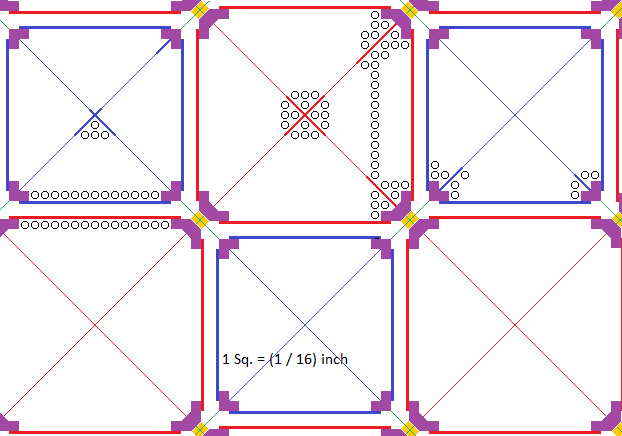
1) In plan view the two different size fuel bundles fit together as shown below:
2) On the above diagram the fixed fuel bundles are shown in red and the movable fuel bundles are shown in blue. The solid purple at the fuel bundle corners indicates the fuel bundle corner girders. Yellow indicates fixed fuel bundle corner spacers which are 0.530 ________inch thick. This spacing and the corner attachments are realized with special fittings to prevent small parts accidentally falling to the sodium pool floor.
3) On the diagram the ordinate parallel and abcissa parallel lines show the positions of the fuel bundle shroud plates. The diagonal lines show the positions of the fuel bundle diagonal plates, although the plate thickness is not to scale. The green lines are layout guide lines.
4) Only a few fuel tubes are shown to indicate how the fuel tubes fit into the fuel bundles with respect to adjacent shroud plates, diagonal plates and corner girders.
5) The maximum fuel bundle width is set by practical limits on the weight of a shielded container needed to transport an irradiated fuel bundle.
6) For bending torque resistance each fuel bundle has four vertical corner girders, two vertical interlocked internal diagonal plates, four vertical external shroud plates, one grating and interlocked adapter plates. The fuel tubes fit within the four nearly triangular spaces defined by the internal diagonal plates, the external shroud plates, the corner girders and the grating. The bottom of each fuel tube is supported by a grating intersection. If necessary the grating can be supported by the adapter plates which are in the same vertical plane as are the diagonal plates.
7) The diagonal plates are interlocked, are internally welded to each other like dividers in a wine carton and are then are internally welded to the corner girders. However in the extended core zone, where fast neutron induced material swelling is anticipated, the diagonal plates are reduced in width by 12.5% and are not welded to the corner girders.
8) A bit of geometry shows that if the diagonal plates replace a diagonal line of wound fuel tubes the maximum possible thickness of a diagonal plate that runs between the wound fuel tubes is:
[2 ((9 / 16)inch)^2]^0.5 - (9 / 16) inch = 0.23299 inch
9) Thus the thickness of the fuel bundle diagonal plates should be:
(3 / 16) inch = 0.1875 inch
thick HT-9.
10) The top of the diagonal plates is at the top of the lifting point allowance. The height of the lifting point allowance is:
26 X (5 /8) inch = 16.25 inch = 0.4064 m
11) The bottom of the diagonal plates is at the top of the grating.
12) The vertical allowance for the assembled fuel tubes with end plugs is:
378 X (5 / 8) inch = 236.25 inch = 6.00 m
13) The grating height is:
5 X (5 / 8) inch = (25 / 8) inch = 0.07935 m
14) Hence the height of the diagonal plates is:
= 6.4 m
15) Each theoretical grating opening is square with a cross sectional area of:
[(9 / 16) inch]^2 - Pi [(3 / 16) inch]^2
= 0.316406 inch^2 - 0.1104466166 inch^2
= 0.20595938 inch^2
= [0.45382 inch]^2
Ideal grating strip thickness = (9 / 16) inch - 0.45382 inch
= 0.1043 inch
The grating strip thickness was chosen to be (1 / 8) inch to meet strength requirements. Hence the actual grating opening per fuel tube is:
[(9 / 16) inch - (1 / 8) inch]^2 = 0.1914 inch^2 = 1.23487 X 10^-4 m^2
16) The fuel tube spacing within a fuel bundle is maintained using a spiral (1 / 16) inch thick stranded wire winding on every fuel tube and by the corner girders, shroud plates and diagonal plates.
17) The fixed fuel bundle corner girders are:
7.9 m ~ 498 X (5 / 8) inch long.
18) The fixed fuel bundle corner girder length allocated to top corner attachment to adjacent fixed fuel bundles, including tool clearance, is:
6 X (5 / 8) inch = 3.75 inch = 0.09525 m.
19)The remaining fixed fuel bundle leg length which extends below the fuel tube bottom is:
1.5 m ~
= 94 X (5 / 8) inch = 58.75 inch = 1.49225 m.
20) The fuel bundle grating transfers the fuel tube load to the fuel bundle corner girders. The adapter plates are positioned directly under the fuel bundle diagonal plates to minimize obstruction of vertical liquid sodium flow. Note that if the 1 inch thick adapter plates support the grating then (3 / 8) inch must be ground off the adapter plate top edges to reduce the adapter plate top edge width to (1 / 4) inch where it touches the grating.
21) The adapter plates of a movable fuel bundle must provide sufficient bending torque resistance. These plates provide a 3.0 inch gap between the top of the support pipe and the bottom of the grating to allow inward radial flow of liquid sodium over the top of the support pipe. The adapter plates also provide a ledge to positively support the movable fuel bundle corner girders.
22) The vertical height of the movable fuel bundle adapter plates is limited by the requirement to provide sufficient movable fuel bundle withdrawal from the matrix of fixed fuel bundles. The extent of this withdrawal is limited to:
1.1 m.
23)CONTINUE FROM HERE
24) On movable fuel bundle adapter plates ~ (1 / 2) inch _______is ground off each side of each vertical edge to properly mate with the movable fuel bundle corner girders.
25) The movable fuel bundle adapter plates each have a 2 X (5 / 8) inch high horizontal top extension that passes over the top of the support pipe and which directly supports the grating. Note that (3 / 8) inch are ground off the top edges.
26) On movable fuel bundles the corner girders extend downwards from the top of the lifting point allowance to 1.25 inch above the bottom of the adapter plates. The adapter plates are welded on to the 8 inch schedule 160 support pipe so as to provide 2 X (5 / 8)____ inch clearance between the top of the support pipe and the bottom of the grating. The top edges of the adapter plate are ground to reduce the adapter plate thickness to (1 / 4) inch at the grating bottom.
27)For the movable fuel bundles the corner girder height is:
(13 + 391 + 26 - 2) X (5 / 8) inch = 428 X (5 / 8) inch
= 267.5 inch = 6.7945 m
28) The rectangular sheet metal enclosure around a fuel bundle is known as its shroud. The shroud provides part of the fuel bundle structural rigidity, positions and physically protects the fuel tubes and excludes particulate matter. The fuel bundle shroud is formed from (1 / 4) inch thick HT-9 sheet steel panels which are outside welded to the corner girders.
29) For the movable fuel bundle the top of the shroud plates is at the top of the corner girders.
30) For the movable fuel bundle the bottom of the shroud plates is at at the grating.
31) For the movable fuel bundles the shroud plate height is:
6.4 m
32) The top of the shroud plates for the fixed fuel bundles is at the top of the lifting point allowance.
33) The bottom of the shroud plates for the fixed fuel bundles is at the grating.
34) Hence the height of the shroud plates for the fixed fuel bundles is:
6.4 m.
35) Each fixed fuel tube bundle has a maximum outside width allowance including tolerances and clearance of:
[23 X (9 / 16) inch] = 12.9375 inches = 0.3286 m
exterior face to exterior face, is 8.001 m high and contains 384 X 6.00075 m high fuel tubes.
36) The width of the fixed fuel bundle shroud plates is:
(23 - 6) X (9 / 16) inch = 9.5625 inch = 0.24288 m
37) Each movable fuel tube bundle has a maximum outside width allowance including tolerances and clearance of:
[19 X (9 / 16) inch] = 10.6875 inches = 0.2715 m
exterior face to exterior face, is 8.001 m high and contains 248 X 6.00075 m high fuel tubes.
38) The width of the movable fuel bundle shroud plates is:
(19 - 4) X (9 / 16) inch = 8.4375 inch = 0.21143 m
39) In the fixed fuel bundles the width of the diagonal plates is:
2^0.5 X 18 X (9 / 16) inch = 14.319 inch = 0.3637 m
40) In the fixed fuel bundles the maximum width of the adapter plates is:
2^0.5 X 18 X (9 / 16) inch = 14.3189 inch = 0.3637 m
41) In the movable fuel bundles the width of the diagonal plates is:
2^0.5 X 15 X (9 / 16) inch = 11.9324 inch = 0.3030 m
42) In the movable fuel bundles the maximum width of the adapter plates is:
2^0.5 X 17 X (9 / 16) inch = 13.5234 inch = 0.3435 m
43) To prevent overall fuel bundle swelling in the core region in that region the diagonal plates are reduced in width by 12.5% and the fuel bundle shroud sheets are not welded to the corner girders to allow both diagonal and shroud sheet swelling in the core region without causing overall horizontal fuel bundle width swelling.
44) Below the grating the fuel bundle legs are stabilized by 0.25 m long thick diagonal fins.
45) The legs of the fixed fuel bundles are corner girder lower extensions and fit over the diagonal fins which are securely fastened to the 1.35 m high fuel bundle bottom probe which is 6.625 inch OD and 4.897 inch ID (6 inch schedule XX pipe)
46) The top corners of the fixed fuel bundles are connected to the top corners of the adjacent fixed fuel bundles by 0.707 inch ____middle spacers and (1 / 2) inch diameter through bolts to form a rigid matrix of fixed fuel bundles within which the movable fuel bundles slide vertically. The spacer thickness is 0.707 ____inches corresponds to a theoretical movable fuel bundle shroud plate outside face to fixed fuel bundle shroud plate outside face separation of 5 / 8 inches.
47) The crane lifting point of the movable fuel bundle is made from a
13 X (5 / 8) inch = 8.125 inch = 0.206375 m
diagonal plate extension above the maximum height of the tops of the fuel tube top plugs. The crane lifting point must be carefully designed to not over stress the diagonal plates.
48) Assume that the crane lifting point consists of four 2.0 inch diameter holes. There should be 4 inches of plate height above the holes and 2 inches of plate below the holes. With 2.0 inch diameter lifting pins, each hole can potentially lift:
2 inch X (3 /16) inch X 10,000 lb / inch^2 = 3750 lbs.
49) In normal reactor operation the movable fuel bundles are raised by screw actuators which are held in position by the open steel lattice. The actuators support the movable fuel bundles and set the amount of insertion of each movable fuel bundle into the matrix of fixed fuel bundles. When the movable fuel bundles are fully withdrawn the actuator hardware keeps the movable fuel bundles upright.
50) The cross sectional area of each fixed fuel bundle corner girder is:
5 x (9 / 16) inch X (9 / 16) inch = 1.582 inch^2
51) The cross sectional area of each movable fuel bundle corner girder is:
3 X (9 / 16) inch X (9 / 16) inch = 0.9492 inch^2
52) For X = (9 / 16) inch the linear center to center distance between similar fuel bundles of:
[23 X (9 / 16) inch + (19 X 9 / 16) inch
= 42 X 9 / 16 inch X.0254 m / inch
= 0.6000 m
Which allows easy horizontal drawing scaling using:
0.6 m = (19 + 23) X (9 / 16) inch
or
1 m = 70 X (9 / 16) inch
53) For the fixed fuel bundles the shroud inside face to shroud inside face distance is:
21 X (9 / 16) inch = 11.8125 inches.
54) For the movable fuel bundles the shroud plate inside face to shroud plate inside face distance is:
17 X (9 / 16) inch = 9.5625 inches.
55) Lifting hole radial position:
The total width of each diagonal plate in the movable fuel bundle is:
15 X (9 / 16) inch X 2^0.5 = 11.9324 inch
56) Hence locate the axis of the 3.0 inch diameter lifting hole about 3.0 inch from the diagonal plate center.
58) WE NEED TO BE CONCERNED ABOUT THE LOCAL SHEER STRESS ON THE DIAGONAL PLATE NEAR THE LIFTING HOLE!
59) MOVABLE FUEL BUNDLE INSIDE PERIMETER LENGTH:
Movable fuel bundle inside perimeter length
= [(number of tubes /movable active fuel bundle) X (Pi X (3 / 8) inch)]
+ (internal sheet metal and girder length per movable active fuel bundle)]
[(248) X (Pi X (3 / 8) inch)]
+ [(13 X (9 / 16) inch X 4) + (4 X 4 X (9 / 16) inch] + 2^0.5 [ 4 X 15 X (9 / 16) inch_]
= [(248) X (Pi (3 / 8) inch)] + [68 X (9 /16) inch] + 2^0.5 [60 X (9 / 16) inch
= [93 Pi inch)] + [85.98 inch]
= [(93 Pi inch)] + 85.98 inch / active movable bundle
= 378.15 inch / active movable fuel bundle
60) FIXED FUEL BUNDLE INSIDE PERIMETER LENGTH:
Fixed fuel bundle inside perimeter length
= [(number of tubes / fixed fuel bundle) X (Pi X (3 / 8) inch)]
+ [(internal sheet metal and girder length per fixed fuel bundle)]
= [(384) X (Pi X (3 / 8) inch)]
+ [15 X (9 / 16) inch X 4] + [4 X 4 X (9 / 16)]
+ [ 1 9 X (9 / 16) inch X 2^0.5 X 4] + [2^0.5 X (9 / 16) inch X 4]
= 144 Pi inch + [76 X (9 / 16) inch] + [80 X (9 / 16) X 2^0.5]
= 144 Pi inch + 106.39 inch / active fixed bundle
= 558.78 inch / active fixed fuel bundle.
61) SLOT LENGTH:
Hence:
Total inside perimeter
2 X (slot length)
= [(378.15 inch / active movable bundle) X (464 active movable bundles)]
+[(558.78 inch / active fixed bundle) X (481 active fixed bundles)]
= 175,461.6 inch + 268,773.2 inch
= 444,234.18 inch
= 444,234.18 inch X 0.0254 m / inch
= 11,283.5 m
Hence the equivalent slot length is:
11,283.5 m / 2 = 5641.8 m
61) MOVABLE FUEL BUNDLE INSIDE OPEN CROSS SECTIONAL AREA FOR SODIUM FLOW:
= + (Number of movable active fuel bundles) X (internal square area of one movable bundle)
- (Number of movable active fuel bundles) X (Number of tubes / movable bundle) X (area per tube)
- (Number of movable active fuel bundles) X (girder area per movable fuel bundle)
- 2 X (diagonal sheet thickness x cross sheet width for movable bundle)
= (464) X [(17 X (9 / 16)]^2 inch^2
- (464) X [(248) X (Pi (3 /16)^2) inch^2]
- (464) X [(4 X 3 X (9 / 16)^2 inch^2)]
- (464) X 2 X (3 / 16) inch x [15 X 2^0.5 X (9 / 16) inch ]
= (464) [277 X (9 / 16)^2 inch^2 - 248 (Pi / 9)(9 / 16)^2 inch^2 - 10( 2^0.5)(9 / 16)^2 inch^2]
= (464)(9 / 16)^2 inch^2 [277 - 248 (Pi / 9) - 10 (2^0.5)]
= (464)(81 / 256) inch^2 [ 277 - 86.568 - 14.142] inch^2]
= 25,881.57 inch^2
= 16.698 m^2
62) FIXED FUEL BUNDLE INSIDE OPEN CROSS SECTIONAL AREA FOR SODIUM FLOW:
+ (Number of fixed active bundles) X (internal square area of one fixed bundle)
- (Number of fixed active fuel bundles) X (Number of tubes / fixed bundle) X (area per tube)
- (Number of fixed active fuel bundles) X (girder displacement area per fixed fuel bundle)
-
- 2 X (diagonal sheet thickness x cross sheet width for fixed bundle)
+ (481) X [(21 X (9 / 16))^2 inch^2]
- (481) X (384) X (Pi (3 / 16)^2) inch^2
- (481) X [22 x (9 / 16)^2 inch^2]
-
- (481) X [2 X (3 / 16) inch x (19 X 2^0.5 X (9 / 16) inch)]
= 481 X (9 / 16)^2 inch^2 [441 - 384 (Pi / 9) - 22 - (2 / 3)(19)2^0.5]
= 481 (81 / 256) inch^2 [419 - 134.041 - 17.913]
= 40,642.106 inch^2
= 26.221 m^2
63) TOTAL ACTIVE OPEN AREA FOR SODIUM FLOW
(movable fuel bundle area) + (fixed fuel bundle area)
= 16.698 m^2 + 26.221 m^2
= 42.918 m^2
This open area is used to calculate the natural sodium flow as afunction of temperature rise.
64) SLOT APPROXIMATION:
In the slot approximation the total liquid sodium flow cross section is:
[((Inside perimeter) / 2) x (slot width) = (Open area)
[(11,283.5 m) / 2] X (slot width) = 42.918 m^2
which gives the slot width as:
(slot width) = 2 (42.918 m^2) / (11,283.5 m)
= 0.007607 m
= 7.607 mm
65) FIND Ro FOR USE IN NATURAL SODIUM FLOW CALCULATION:
Hence:
Ro = .007607 m / 2
= .0038036 m
This Ro value is used to calculate the natural sodium flow as a function of temperature rise.
FUEL BUNDLE VERTICAL STRUCTURE:
1) The fuel tube height is set by FNR design calculations relating to the core height, blanket thickness and plenum height. This height is further constrained by material length availability.
2) In the fixed fuel bundle below the adapter plates open diagonal cross bracing is used to increase the legs bending torque resistance. In the case of the fixed fuel bundles the bottom of the legs must be square so as to fit into cast sockets mounted on the open steel lattice. There must also be sufficient open space through the cross bracing to allow lateral liquid sodium circulation.
3) An important issue in earthquake protection is fastening the fixed fuel bundles together at their top corners to form a rigid fixed fuel bundle matrix. It is important to prevent liquid sodium, which can slosh back and forth during an earthquake, from significantly changing the fuel assembly geometry and hence its reactivity.
4) In order to meet the bending torque resistance requirements the corner girders of movable fuel bundles must physically overlap the 6 inch schedule XX probe pipe (6.625 inch OD, 4.897 inch ID) by about:
0.25 m = 6.8425 inch
5) The probe end tip must have a tapered lower end to assist in blind insertion into its support pipe.
SECONDARY VERTICAL DIMENSIONS:
1) Fuel tube length:
378 X (5 / 8) inch = 236.25 inch = 6.00075 m
2) Fuel tube end plug length:
= 4 X (5 / 8) inch X 0.0254 m / inch = 0.0635 m
3) Fuel tube end plug penetration of fuel tube:
= 2 X (5 / 8) inch X 0.0254 m / inch = 0.03175 m
4) Fuel tube end plug projection beyond the fuel tube:
= 2 X (5 / 8) inch X 0.0254 m / inch = 0.03175 m
6) Grating height:
= 5 X (5 / 8) inch X.0254 m / inch = 0.079375 m
7) Assembled height of grating + fuel tube plugs + fuel tubes:
= (5 + 2 + 384 + 2) X (5 / 8) inch X 0.0254 m / inch
= (393) X (5 / 8) inch X 0.0254 m / inch
= 6.238 m
8)
9) Bottom end plug shoulder length:
= 1 X (1 / 8) inch X 0.0254 m / inch = 0.015875 m
10) Top end plug shoulder length = 2 (1 / 8) inch
11) Top end plug (3 / 8) inch OD machined section:
= 3 (5 / 8) inch - (2 / 8) inch = (13 / 8) inch
12) Top end plug (3 / 8) inch threaded length:
(13 / 8) inch - (1 / 8) inch = (12 / 8) inch
13) Fuel tube inside length:
= (378 - 4) X (5 / 8) inch X 0.0254 m / inch
= (374) X (5 / 8) inch X 0.0254 m / inch
= 5.93725 m
14) Five Rod Blanket Stack:
113 X (5 / 8) inch X 0.0254 m / inch = 1.7939 m
15) Core Rod:
38 X (5 / 8) inch X0.0254 m / inch = 0.60325 m
16) Plenum:
(374 - 113 - 38 - 113) X (5 / 8) inch X 0.0254 m / inch
= 110 X (5 / 8) inch X 0.0254 m / inch
= 1.74625 m
17) Recall that lifting point vertical allowance ia:
13 X (5 / 8) inch = 8.125 inch
18) Lifting hole = 2.00 inch diameter
Hence we can have 4.125 inch of (1 / 4) inch steel plate above the lifting hole and 2.000 inch of clearance below the lifting hole.
Probe pipe is: 6.625 inch OD X 4.897 inch ID X 1.35 m long.
Probe pipe mass is:
{Pi [(6.625 inch)^2 -(4.897 inch)^2]/ 4) X 1.35 m X (.0254 m / inch)^2 X (7850 kg / m^3)
= Pi [43.8906 inch^2 - 23.9806 inch^2] x 1.70927 kg / inch^2
= 106.913 kg
SUMMARY OF COMPONENT VERTICAL DIMENSIONS:
Fixed Fuel Bundle Corner Girders = 504 X (5 / 8) inch
Fixed Fuel Bundle Corner Bolting Girder Extension = 6 X (5 / 8) inch
Fixed Fuel Bundle Crane Lift Point Allocation = 13 X (5 / 8) inch
Fixed Fuel Bundle Fuel Tube, Grating, Plug and Differential Expansion Allowance
= 391 X (5 / 8) inch
Grating Height = 5 X (5 / 8) inch
Diagonal Plate Height = (13 + 391 - 5) X (5 / 8) inch
= 399 X (5 / 8) inch
Fixed Fuel Bundle Adapter Plate Height = 26 X (5 / 8) inch
Fixed Fuel Bundle Shroud Plate Height:
(13 + 391 + 26) X (5 / 8) inch
= 430 X (5 / 8) inch
Fixed Fuel Bundle Leg Length Below Grating
= (504 - 6 - 13 - 391) X (5 / 8) inch
= 94 X (5 / 8) inch
End plug overall height = 5 X (5 / 8) inch
End plug penetration of fuel tube = 2 X (5 / 8) inch
Fuel tube = 378 X (5 / 8) inch
Active fuel tube Blanket rod stack = 113 X (5 / 8) inch
Core rods = 38 X (5 / 8) inch
Active fuel tube Plenum = 110 X (5 / 8) inch
Movable Fuel Bundle Crane Lift Point Allowance = 13 X (5 / 8) inch
Movable Fuel Bundle Fuel Tube, Grating, Plug, Space Allowance
391 X (5 / 8) inch
Grating = 5 X (5 / 8) inch
Diagonal Plate Height
= (13 + 391 - 5) X (5 / 8) inch
= 399 X (5 / 8) inch
Movable Fuel Bundle Adapter Plate Height = 26 X (5 / 8) inch
Movable Fuel Bundle Corner Girders:
= 6.4 m
= 6.4 m
Movable Fuel Bundle Shroud Plate Height:
6.4 m
Probe top to Grating top Gap = 0.15 m
Probe Length
= 1.35 m
Fuel:
Active Fuel Tube Blanket Rod Stack = 113 X (5 / 8) inch
Core Rod = 38 X (5 / 8) inch
Active Fuel Tube Plenum = 110 X (5 / 8) inch
FUEL TUBE SPACING:
1) The fuel tube OD and ID are in part constrained by material availability.
3) To maintain sufficient primary liquid sodium flow by natural circulation the fuel tubes are positioned on a square grid so that the liquid sodium coolant passages between the fuel tubes remain open in the presence of fuel tube swelling. A square grid lends itself to square fuel bundles that have good reactor power modulation characteristics. However, a problem with a simple array of identical square fuel bundles is that the array lacks horizontal mechanical structural stability, especially in earthquake conditions.
4) In order to achieve both good liquid sodium natural circulation, which requires fuel tubes on a square grid, and good horizontal structural stability alternating movable and fixed fuel bundles of different sizes are used. Fixed fuel bundles are wider than movable fuel bundles, act as slide guides for movable fuel bundles and require different support arrangements than movable fuel bundles.
5) Within each fuel bundle the fuel tube bottoms are positioned by a horizontal square grid which is (9 / 16) inch center to center. This grid is square to ensure sufficient primary liquid sodium natural circulation in the presence of 12.5% linear fuel tube swelling. The fuel tube height is set by FNR design calculations relating to the core height, blanket thickness and plenum height. The fuel tube OD and length are in part constrained by material availability. The fuel tube center to center distance in the fuel tube bundle was found by itterative liquid sodium flow and fuel reactivity calculations. The maximum number of tubes in a fuel bundle is set by the shielded container weight constraint for a lead container of sufficient wall thickness for certain transportation biosafety.
6) Each fuel tube bottom plug has (1 / 8) inch wide point for mating with the fuel bundle bottom grating which is formed from (1 / 8) inch thick steel sheet. The fuel tube top plugs have (1 / 4) inch threads to allow easy selective grasping for controlled insertion, rotation or withdrawal of each individual fuel tube.
7) The size of the minimum gap between adjacent steel fuel tubes is set by reactivity requirements with old fuel. As the gap between the fuel tubes becomes smaller the problems of primary sodium circulation and of filtering particulates out of the liquid sodium rapidly become larger. As the gap becomes larger the required core rod fissionable material concentration rapidly increases.
8) In choosing the gap between the steel fuel tubes in each fuel bundle the issue is one of maximizing the average fuel density in the fuel bundle while not unduely obstructing the liquid sodium coolant circulation and not imposing unreasonable cleanliness restrictions on the liquid sodium pool.
9) The spacing between adjacent fuel tubes is maintained by a (1 / 16) inch OD to (3 / 32) inch OD spiral stranded wire winding on every fuel tube. These spiral windings are spot welded onto their respective fuel tubes. Fuel tube spacing control is further enhanced by geometries of the shroud plates, diagonal plates and corner girders
10) In the channels between the fuel tubes liquid sodium coolant flows upwards to remove heat. Implications of this design are natural sodium circulation, negligible fuel tube erosion, reasonable fuel temperature, reasonable reactor dimensions, an acceptable liquid sodium temperature rise and a reasonable requirement with respect to filtering particulates out of the liquid sodium.
11) The fuel tube wire winding thickness and pitch must ensure sufficient liquid sodium flow to a reactor hot spot to prevent formation of gaseous coolant bubbles (voids). If voids form the buoyancy force will be increased but the coolant mass flow might be reduced. We must check that there is no region of coolant thermal instability as the coolant flow cross section decreases or as the core fuel temperature increases.
12) A related issue is that the allowable maximum sodium temperature rise as liquid sodium passes through the fuel bundle is theoreticaly limited at the low end by the melting point of NaOH (318 deg C) and at the high end by certainty of avoiding Pu melting on the fuel rod axis (639 deg C) and Pu-Fe fuel tube eutectic melting (602 degrees C) at the fuel tube inner surface.
13) In practise there are a number of temperature drops and other issues which must be taken into consideration which impose a lower limit on the liquid sodium coolant working temperature of about 340 degrees C and an upper limit on the liquid sodium coolant high working temperature of about 460 degrees C.
14) Based on these issues the fuel tube outside diameter (OD) was chosen to be:
0.375 inch
and the square lattice center to center spacing between adjacent fuel tubes was chosen to be:
(9 / 6)) inch = 0.5625 inch.
15) This dimension choice sets the normal average smallest initial intertube gap in the fuel bundle at:
(3 / 16) inch
which might reduce to:
(1 / 8) inch
after 12.5% linear fuel tube swelling, so filtering should be used to eliminate dirt particulates larger than (1 / 16) inch in longest dimension.
16) Each fuel tube position has associated with it a plan view top surface area of about
1 tube per [0.5625 inch]^2
= 1 tube / .3164 inch^2
17) The cross sectional area initially occupied by each unwound fuel tube is:
Pi (3 / 16)^2 inch^2 = 0.11044 inch^2
18) The coresponding open area for sodium flow is:
[(9 / 16) inch]^2 - 0.11044 inch^2
= 0.3164 inch^2 - 0.11044 inch^2
= 0.20596 inch^2
19) Over the working life of a fuel tube its OD in the core zone might swell from 0.375 inch to
1.125 X 0.375 inch:
.
Hence in the core zone the fuel tube cross sectional area might swell to:
Pi [1.125]^2 [(0.375 / 2) inch]^2 = .13978 inch^2
20) Thus the remaining cross sectional open area per active fuel tube available for natural convection liquid sodium coolant flow past the fuel tubes is:
0.3164 inch^2 - 0.13978 inch^2 = 0.17662 inch^2
= 0.17662 inch^2 X (.0254 m / inch)^2
= 1.13948 X 10^-4 m^2
FUEL BUNDLE GRATING:
The fuel tubes in a fuel bundle are held in position by the (1 / 8) inch thick sheet steel grating directly under the fuel tubes. The grating transfers the weight of the fuel tubes onto the adapter plates and then to either a fixed fuel bundle legs or to a movable fuel bundle support pipe. It is of paramount importance that the fixed fuel bundle adapter plate welds never structurally fail. Hence these welds must be tested at 3X their normal maximum load.
The grating strips need to be (1 / 8) inch thick. Then the grating the open area per fuel tube is:
(7 / 16) inch X (7 / 16) inch X (.0254 m / inch)^2 = 1.23487 X 10^-4 m^2 / fuel tube.
Thus the grating open are is the smallest open cross sectional area in the main sodium flow path.
The corresponding cross sectional area of total sodium flow is:
299,776 active fuel tubes X 1.23487 X 10^-4 m^2 / fuel tube
= 37.0186 m^2
This is the smallest cross sectional area in the reactor sodium circulation loop. This data is carried forward to the advanced sodium flow calculations.
HORIZONTAL SODIUM FLOW:
The maximum open area around the fuel tubes is:
[0.20596 inch^2 / active fuel tube] X (.0254 m / inch)^2 X 299,776 active fuel tubes
= 39.83 m^2
24) Hence the vertical thickness of the radially horizontally moving liquid sodium layer at the reactor active region perimeter is about:
(39.83 m^2) / (31.4 m) = 1.27 m.
SLOT APPROXIMATION:
For viscosity analysis purposes we can approximate the liquid sodium flow up past a fuel tube as a flow through a slot. Initially the length of the slot is half the perimeter length of the fuel tube or
Pi (1 / 2) inch (1 / 2) = 0.7854 inch
= 0.7854 inch X (.0254 m / inch) = 0.01995 m
Initially the open area is dominated by the grid open area, so the equivalent slot width is:
1.0521 X 10^-4 m^2 / 0.01995 m = 0.005274 m
After the fuel tube swells causing its diameter to increase by (1 / 16) inch the equivalent length of the slot becomes:
Pi (9 / 16) inch (1 / 2) = 0.8836 inch
= 0.8836 inch X 0.0254 m / inch = 0.02244 m
At this time the open area is core zone limited to:
9.168 X 10^-5 m^2
which gives an equivalent slot width of:
(9.168 X 10^-5 m^2) / (0.02244 m) = 0.004086 m
CORE ZONE FUEL SWELLING:
Practical operating experience with the EBR-2 reactor showed that during normal operation formation of fission products causes the core fuel rod cross sectional area to swell by about 33%. Hence the initial reactor core fuel rod diameter is restricted to:
[(steel fuel tube ID) X 0.86].
The only practical ways to increase the average fuel density in the reactor core are to either reduce the gap between the steel fuel tubes or to increase the concentration of Pu-239 in the core fuel rods. Note that the initial blanket fuel rod outside diameter can be slightly larger than the initial core fuel rod outside diameter because the blanket fuel rods are less subject to fast neutron and fission product induced swelling.
CORE ZONE STEEL SWELLING
Due to the action of fast neutrons the fuel bundle material in the extended core region will swell. It is important that in this region the fuel bundle can lenthen due to swelling but must not get wider. Otherwise the overlapping fuel bundles could jam. It is not practical to space the fuel bundles further apart to prevent this jamming, as that spacing will substantially reduce the average Pu-239 concentrations making attainment of core criticality difficult with old fuel.
In the extended core zone it is necessary to reduce the width of the fuel bundle diagonal reinforcing plates and to not weld these plates to the corner girders. The fuel bundles must be designed so that the extended core section of the fuel bundle can safely absorb the maximum torque associated with crane handling of the fuel bundles.
The present fuel bundle design provides at room temperature an ideal (3 / 4) inch clearance between the outer surface of the shroud plate of a movable fuel bundle and the outer surfce of the shroud plate of the adjacent fixed fuel bundles. With good dimensional tolerance control this clearance should be sufficient to allow reasonable core zone material swelling and thermal expansion. Note that in addition to fabrication tolerances this (3 / 4) inch space must absorb corner girder swelling and thermail expansion.
THERMAL EXPANSION:
Note that the open steel lattice near the bottom of the primary liquid sodium pool will thermally expand with increasing surrounding liquid sodium temperature. During normal reactor operation the open steel lattice is likely to be about 120 degrees C cooler than the liquid sodium temperature at the top of the fuel bundle. Hence the differential horizontal width thermal expansion per fuel bundle is approximately:
20 ppm / deg C X 120 deg C X 13.125 inch = 0.039 inch
The fuel bundle leg sockets must accommodate this differential thermal expansion.
An important issue is that fuel rod thermal expansion must be harnessed to contribute to the drop in reactivity with increasing temperature. This objective is achieved by adding a bottom spring under each stack of fuel rods
within movable fuel bundles and by adding a fuel tube pinch point near the top of the blanket fuel rod in each movable bundle fuel tube. Then top thermal expansion causes the core rods in the fixed fuel bundles to move up and causes the core rods in the movable fuel bundles to move down. Note that we need a reliable high temperature spring material.
SWELLING AND THERMAL EXPANSION ALLOWANCE:
Over the working life of a fuel bundle the component linear dimensions in the reactor extended core region can potentially increase by as much as 12.5%. This swelling primarily occurs near the reactor core, not at the top and bottom of a fuel bundle where the fast neutron flux is small. Nevertheless the fuel bundle design must accommodate this swelling. To achieve certain cool shutdown the fully swollen movable fuel bundles must still freely slide within the swollen portions of the surrounding fixed fuel bundles. Periodic demonstration of this free sliding is an important long term safety issue. Fuel bundles must also be engineered to prevent fuel bundle warping.
The fuel bundles are designed so that individual fuel tubes, corner girders and diagonal plates can all linearly swell due to fast neutron bombardment in and adjacent to the core zone without the external width of the fuel bundle significantly changing. In the core zone the diagonal plates are reduced in width to provide a swelling allowance and the shroud plates are not welded to the corner girders.
Fuel bundles are intended to be replaced at 12.5% linear swelling of the most intensely neutron irradiated sections occurs. The fuel tube array center-to-center spacing is established by the support grid bottom geometry, by the spiral windings on every second fuel tube and by the corner girders, diagonal plates and shroud plates.
At the upper corners of the fixed fuel bundles are through bolts with spacers which are used to corner connect adjacent fixed fuel bundles and to prevent adjacent fixed fuel bundles sliding axially with respect to one another and hence prevent lateral rocking as might occur during a severe earthquake. At a corner spacer thickness of 0.707 inch the theoretical space between adjacent shroud plates is (3 / 4) inch.
CLEARANCE PENETRATIONS:
The extent of the movable fuel bundle corner girder penetration of the (3 / 4) inch clearance due to swelling is:
(1 / 8) X (10 / 8) inch X (1 / 2) = (10 / 128) inch
The extent of the fixed fuel bundle corner girder penetration of the (3 / 4) inch clearance due to swelling is:
(1 / 8) X (15 / 8) inch X (1 / 2) = (15 / 128) inch
The extent of the movable fuel bundle corner girder penetration of the (3 / 4) inch clearance due to thermal expansion is:
500 deg C X 20 / 10^6 deg C X 19 X (5 / 8) inch X (1 / 2) = 0.059375 inch
The extent of the fixed fuel bundle corner girder penetration of the (3 / 4) inch clearance due to thermal expansion is:
500 deg C X 20 / 10^6 deg C X 23 X (5 / 8) inch X (1 / 2) = 0.071875 inch
Thus the remaining clearance between the shroud plates available to accommodate fabrication tolerances is:
0.75 inch - (10 / 128) inch - (15 / 128) inch - 0.059375 inch - 0.071875 inch
= 0.75 inch - 0.1953 inch - 0.059375 inch - 0.071875 inch
= 0.4234 inch
FIXED FUEL BUNDLE DETAIL:
Each fixed fuel bundle is formed from double angle corner girders with side arms at 45 degrees to the base that displace 6 theoretical fuel tube positions at each corner. In addition there are 33 theoretical fuel tube positions displaced by reinforcing diagonal plates. Hence the actual number of fuel tubes contained in a fixed fuel bundle is:
21^2 - 4(6) - 33 = 384 fuel tubes
A fixed fuel bundle has corner girders which extend up past the fuel tubes and attach to the diagonal sheets that provide a central lifting point. On installation the corner girders of fixed fuel bundles connect to adjacent fixed fuel bundles by through bolts at the top of each corner girder and by sockets at the bottom of each corner girder lower leg extension to form a rigid matrix into which the smaller movable fuel bundles can be inserted. The sockets are firmly attached to the open steel support lattice. The sockets are tapered at their tops to allow practical blind mating with the fuel bundle legs with +/- 6 mm (+/- (1 / 4) inch) position error.
Once the fixed fuel bundles are installed their sockets keep the fixed fuel bundles faces parallel to the faces of the other fuel bundles.
The entire weight of the fixed fuel bundles is supported by lower corner girder extensions (legs). These legs extend ~ 1.5 m below the fuel tube bottoms to allow movable fuel bundle travel, to allow liquid sodium to easily flow into the bottom of the fuel bundles and to minimize long term fast neutron damage to the open steel lattice. These legs are stabilized by reinforcing diagonal bracing.
The fixed fuel bundle shroud plates are:
[17 (9 / 16)] inch wide X (3 / 16) inch thick.
= 1.7929 in^2 in plan view cross sectional area
The bottom of each fixed fuel bundle leg is supported by half of an "E" socket that overlaps the fixed fuel bundle area allocation. With reference to the previous diagram the cross sectional area of each fixed fuel bundle double angle corner girder is:
[5 X (9 /16) X (9 / 16)] inch^2
= 1.582 inch^2
The fixed fuel bundle diagonal plates are:
(3 / 16) inch thick X [(2)^0.5 X (23 - 5)(9 / 16) inch] wide
= 2.684 in^2 in cross sectional area
MOVABLE FUEL BUNDLE DETAIL:
In operation each movable fuel bundle's weight is borne by its actuator which sets the amount of movable fuel bundle insertion into the matrix of fixed fuel bundles.
The movable fuel bundle travel is limited at its fully retracted position by the adapter plates and at its highest position by a the actuator threaded shaft.
There is a keyway to precisely rotationally orient a movable fuel bundle at its fully retracted position.
Each movable fuel bundle consists of diagonal reinforcing plates, corner girders and a shroud surrounding 248 vertical fuel tubes. A movable fuel bundle withdraws up to 1.0795 m relative to the fixed fuel bundle matrix to set the reactor operating temperature and to cause a reactor cool shutdown. The vertical position of each movable fuel bundle is set by its actuator and is indicated by its Indicator Tube.
At the 4 corners of every movable fuel bundle are angle girders that displace 3 theoretical fuel tube positions at each corner. In addition there are 29 theoretical tube positions occupied by reinforcing diagonal plates. Hence the actual number of fuel tubes contained in a movable fuel bundle is:
17^2 - (4 X 3) - 29 = 248 fuel tubes
The movable fuel bundles have corner girders with sides that are each:
2 (9 / 16) inch = (9 / 8) inch long. The material is (9 / 16) inch thick. With reference to the previous diagram the cross sectional area of each such corner girder is:
3 X (9 / 16) inch X (9 /16) inch
= (243 / 256) inch^2
= 0.9492 inch^2
The movable fuel bundle diagonal reinforcing plates are (3 /16) inch thick The width of each of these plates is:
(2)^0.5 X 15 X (9 / 16) inch = 11.9324 inch
The cross sectional area of each movable fuel bundle diagonal plate is:
(3 / 16) inch X 11.9324 inch = 2.237 inch^2
The probe pipe has a tapered bottom tip which aids blind insertion into the actuator.
One purpose of this arrangement is to hold the movable fuel bundle nearly vertical in the fully retracted position and properly oriented while its surrounding fixed fuel bundles are being installed. Once the fixed fuel bundles are in position the movable fuel bundle support pipe acts as a piston rod.
LOADING AND UNLOADING FUEL BUNDLES:
It is important to never let the fuel assembly accidentaly go critial. In loading fuel bundles into the sodium pool each movable bundle should be installed in its fully withdrawn and straight upright and aligned position before installing its surrounding fixed fuel bundles. The rotational alignment in the fully withdrawn state is achieved via a keyway. (DETAIL)
Similarly the fixed fuel bundles surrounding a movable bundle should be extracted from the fuel assembly before extracting the movable fuel bundle. That strategy ensures that the fuel assembly will not accidently go critical due to pulling a movable fuel bundle right through the matrix of fixed fuel bundles.
Thus the order of fuel bundle insertion and extraction is important. In assembly of the fuel bundle array a movable fuel bundle is ALWAYS installed fully retracted before its surrounding fixed fuel bundles are installed. Similarly, during disassembly of the fuel bundle array the fixed fuel bundles surrounding a movable fuel bundle are ALWAYS removed before removing the retracted movable fuel bundle.
USED FUEL COOLING:
Used active fuel bundles are held in the outer two rings of the assembly of fuel bundles to permit fission products to naturally decay while the fuel bundles remain immersed in liquid sodium. While cooling in the outer two fuel bundle rings with movable bundles fully withdrawn the used active fuel bundles will act as additional passive fuel bundles.
ORDER OF FUEL BUNDLE FABRICATION:
The order of fabrication of the fuel bundles is important to allow the required welding. The contemplated order is as follows:
a) Cut diagonal plates to size. Center cut them half way down their length.
b) Interlock the diagonal plates together like dividers in a wine box.
c) Weld the diagonal plates together along their lengths.
d) Weld the corner girders to the diagonal plates. Note that there is no welding near the core zone due to diagonal plate width reduction.
e) Insert the grating.
f) Weld the adapter plates to the movable fuel bundle support pipe.
g) Weld the tapered centering devices to the support pipe.
[1.00 inch wide X (9.562 inch - 8.625 inch) / 2 inch]
= 1.00 inch wide X 0.4685 inch thick
at top.
h) Weld the adapter plates to the corner girders.
i) Check the mechanical strength of the adapter plate support of the grating.
j) Weld on the shroud sheets with just external welds.
k) Attach the filter housings and filters as applicable.
l) Check the entire fuel bundle basket for dimensional compliance.
m) Insert the fuel tubes.
n) Apply a temporary fuel tube retainer plate.
FUEL BUNDLE CRANE LIFTING:
The fuel bundles are designed to be sufficiently robust to permit reasonable crane handling. It must be practical to use a crane to lift a fuel bundle by its lifting point from a horizontal position to a vertical position without the fuel bundle being deformed by its own weight. This fuel bundle bending torque resistance requirement implies a transverse acceleration resistance of 0.5 g when the fuel bundles are bottom supported. This bending torque resistanc requirement sets minimums on the thickness of the fuel bundle shroud plates, diagonal plates, corner girders, support pipe and leg bracing.
The lifting point for a fuel bundle is a group of four holes in 0.25 inch thick diagonal plates. These diagonal plates and the corresponding corner girders and shroud plates extend:
13 X (5 / 8) inch = 8.125 inch
above the maximum height of the fuel tube top plugs.
Four 2 inch diameter holes in these plates form a lifting point with a maximum lifting capacity of:
4 X 2 inch X (1 / 4) inch X 10,000 lbs / inch^2 = 20,000 lbs = 10 tons.
Note that the crane lifting device is a special four pin device that provides one snugly fitting pin for each hole in the diagonal plates. The four pins have expanded ends which engage four holes located near the top of the diagonal sheets.
The diagonal plates forming the lifting point must not obstruct primary liquid sodium flow and must not prevent individual fuel tube insertion or extraction. The fuel tube top plugs have (3 / 8) inch threads and the OD of the fuel tube insertion / removal tool cannot be more than (5 / 8) inch.
The corner girders of the fixed fuel bundles must project upwards above the top of the diagonal plates by about:
6 (5 / 8) inch = 3.75 inch
to allow for a 3.5 inch long 0.5 inch diameter horizontal bolt fastening to adjacent fixed fuel bundles at the top of the corner girders.
The bottom of the fuel bundle lifting point holes must be at least 2 inch above the top of the fuel tube top plugs.
INDICATOR TUBE:
There are 7.5 m high buoyant indicator tubes field attached to the movable active fuel bundles. The vertical position of each movable fuel bundle is visually indicated by the 0.3 m to 1.5 m exposed height of the top of its indicator tube above the primary liquid sodium surface.
Each indicator tube: shows the actual vertical position of its corresponding movable square fuel bundle, allows measurement of the gamma flux emitted vertically by the movable fuel bundle and allows determination of that movable fuel bundle's steady state discharge temperature.
The thermal power output from a movable fuel bundle is approximately proportional to the gamma flux propagating up the hollow portion of its indicator tube.
The steady state movable fuel bundle discharge temperature is indicated by the liquid sodium temperature inside the indicator tube.
Indicator tubes are attached to the movable fuel bundles after the movable fuel bundles are installed and are removed before the movable fuel bundles are relocated. The indicator tube attachment point is the movable fuel bundle lifting point. The indicator tubes should be thin wall for buoyancy to keep each indicator tube upright. The indicator tube diameter should be minimal to minimize obstruction of liquid sodium flow, but must be sufficient to allow accurate movable fuel bundle liquid sodium discharge temperature measurement. The difference between the indicator tube OD and ID provides a hollow path for gamma radiation to reach the overhead FNR monitoring apparatus.
An indicator tube isolates a movable fuel bundle's hot liquid sodium discharge stream from the temperature of the surrounding liquid sodium. This isolation ensures that the temperature in the middle of the indicator tube reflects the temperature of the movable fuel bundle sodium discharge. The hollow walls of the indictor tube also provide positive buoyancy so that when 1.5 m of the indicator tube is projecting above the primary liquid sodium surface the indicator tube still maintains a firm upright position.
Note that the buoyancy of the hollow wall indicator tube is not sufficient to lift the net weight of a movable fuel bundle when the indictor tube is fully immersed in liquid sodium. However, the indicator tube must be buoyant in liquid sodium even when at its maximum height.
Indicator Tube: 5.563 inch OD X 0.258 inch wall X 4.5 m long_______
Mass = Pi X 5.563 inch X 0.258 inch X 4.5 m X (.0254 m / inch)^2 X 7.874 X 10^3 kg / m^3
= 103.074 kg_______________
OPEN STEEL SUPPORT LATTICE:
The 1.5 m high open steel support lattice supports the entire weight of the fuel bundles and positions and horizontally stabilizes the actuators. This open steel lattice provides sufficient distance separation between the fuel bundles and the bottom of the sodium pool to ensure that there is no long term deterioration of the stainless steel pool bottom due to neutron absorption. This open lattice also allows free circulation of liquid sodium beneath the fuel tubes. A 8 inch schedule 160 support pipe maintains separation between the bottom of the movable fuel tubes and the actuator jack screw. This separation extends the working life of the actuators. The fixed fuel bundle legs keep the bottom of the fixed fuel bundle tubes 1.5 m above the open steel lattice to protect the open steel lattice from neutron damage. The cross fittings mounted on the top of the open steel lattice fit inside the fixed fuel bundle legs and correctly position the fixed fuel bundles. Blind insertion is assisted by the upright position of the four adjacent retracted movable fuel bundles. A fixed fuel bundle can be released from its socket by removing its 4 top corner "E" fitting bolts and then lifting the fixed fuel bundle using the overhead gantry crane.
BENDING TORQUE RESISTANCE CONSIDERATIONS:
A major issue in fuel bundle design is its bending torque resistance because the overall fuel bundle height of 8.001 m is much greater than its width (.2715 m for movable fuel bundles or 0.3268 m for fixed fuel bundles). Hence, the mechanical design of the fuel bundles is important to ensure that during fabrication, transport, installation and operation the fuel bundles do not deform. Such deformation could potentially cause a jam in the sliding of a movable fuel bundle within the surrounding matrix of fixed fuel bundles.
A fixed fuel bundle has corner girders which extend up past the fuel tubes. These girders top attach to adjacent fixed fuel bundles by through bolts at the top of each corner girder. The fixed fuel bundle positioning cross members are firmly attached to the open steel support lattice. The cross members are tapered at their tops to allow practical blind mating with the fixed fuel bundle legs.
The entire weight of the fixed fuel bundles is supported by lower corner girder extensions (legs). These legs extend ~ 1.5 m below the fuel tube bottoms to allow movable fuel bundle travel, to allow liquid sodium to easily flow into the bottom of the fuel bundles and to minimize long term fast neutron damage to the open steel lattice. These legs are stabilized by reinforcing diagonal members located above the positioning cross members.
In operation each movable fuel bundle's weight is borne by its actuator jack screw which sets the amount of movable fuel bundle insertion into the matrix of fixed fuel bundles. The movable fuel bundle travel is limited at the bottom by the support support pipe length (1.1 m) and at the top by the actuator jack screw length.
The fuel tube spacing within a fuel bundle is maintained using a spiral (1 / 16) inch diameter stranded wire winding spot welded onto every fuel tube and by the diagonal and shroud plates.
REACTOR TEMPERATURE SETPOINT CONTROL:
In normal reactor operation the movable fuel bundles insert into the matrix of fixed fuel bundles from the below. When all the movable fuel bundles are fully inserted into the fixed fuel bundle matrix the reactor is at maximum reactivity. When all the movable fuel bundles are 1.1 m withdrawn from the fixed fuel bundle matrix the reactor must be subcritical. The fuel bundle geometry limits the range of acceptable Pu concentrations in the core fuel rods.
From a power control perspective each movable fuel bundle and its surrounding active fixed fuel bundles can almost be regarded as an independent FNR. Each movable fuel bundle has its own discharge temperature which is set by the amount of insertion of the movable fuel bundle into the fixed fuel bundle matrix. Under cold shutdown conditions all the movable fuel bundles are withdrawn 1.1 m with respect to the fixed fuel bundle matrix.
When the movable active fuel bundles are fully inserted into the fixed fuel bundle matrix there is a ~ 1.5 m high nearly open space outside the movable fuel bundle support pipes that allows almost unimpeded liquid sodium circulation.
BLOCKED COOLANT FLOW CHANNELS:
Between every set of four adjacent fuel tubes is a coolant flow channel. If one isolated coolant flow channel becomes blocked by a distorted fuel tube, dirt or debris the cooling of each of these four adjacent fuel tubes is reduced by 25% and the temperature rise along these fuel tubes potentially increases by 33%. If two adjacent coolant flow channels are blocked the flow of coolant for the most affected fuel tubes is reduced by 50% and the temperature rise along these fuel tubes potentially increases by 100%. Hence, fuel bundles should be designed so that the fuel bundle can safely accommodate a 100% increase over normal in the cooling fluid temperature rise along the fuel tube.
There are really two constraints, one is the safe maximum coolant temperature and the other the the safe maximum fuel temperature. Of these two, normally the maximum fuel temperature is the more confining upper limit. If the maximum allowable temperature rise is:
100 degrees C,
normal coolant temperature rise along the fuel tube must be less than:
(1 / 2) X 100 deg C = 50 degrees C
which implies a worst case sodium operating temperature range from 410 deg C to:BR>
410 deg C + 100 deg C = 510 C deg C
and a worst case fuel centerline operating temperature range of:
460 deg C + 100 deg C = 560 deg C.
FUEL BUNDLE INLET FILTERS:
At the bottom of each fuel bundle are potentially 4 filter sections between and supported by the adapter plates. The purpose of these filters is to prevent particulate matter suspended in the liquid sodium from blocking the cooling flow channels between adjacent fuel tubes. These filters should prevent flow of any particulate matter with any dimension greater than (1 / 32) inch. The filter material is mounted at a 60 degree angle to horizontal to increase its open area.
Downstream from the filter material is an empty space that allows redistribution of sodium flow in the event that one of the filter sections becomes obstructed. Every practical means should be used to keep particulate material out of the sodium pool. The lower portion of the sodium pool should be kept above 330 degrees C to prevent NaOH precipitation on intermediate heat exchange surfaces and on the filters. Operating at 410 degrees C avoids the melting points of KOH, MgOH, Al(OH)3, etc. In the event that a filter is partially plugged the liquid sodium circulation through that filter will decrease causing the fuel bundle's discharge temperature to increase and the gamma/neutron output to fall, indicating a problem with a flow obstruction of that fuel bundle.
Note that any potassium in the liquid sodium will tend to precipitate out at about 360 deg C. From time to time the reactor should be run at no load until the bottom of the sodium pool is at a high temperature to anneal the fuel tubes and to remove potassium deposits.
FIXED FUEL BUNDLE MASS:
From FNR Fuel Tubes each active fuel tube has a mass of 3.7915 kg
The mass of the four fixed fuel bundle corner girders is:
4 X 1.5820 inch^2 X 8.001 m X (0.0254 m / inch)^2 X 7.870 X 10^3 kg / m^3
= 257.0709 kg
Forming the outer shroud on each fixed fuel bundle are 4 X (1 / 4) inch thick steel plates, each [17 X (9 /16) inches] X 268.75 inch. The volume of these shroud plates is:
4 X 17 X (9 / 16) inch X 6.1 m X (1 / 4) inch X (.0254 m / inch)^2 = 0.03763 m^3
The mass of the fixed fuel bundle shroud plates is:
+ (0.03762 m^3) X 7.870 X 1000 kg / m^3
= 296.17 kg
The fixed bundles have two diagonal reinforcing plates, each:
2^0.5 X 18 X (9 / 16) inch = 14.319 inches wide. The mass of the diagonal sheets is:
2 X 14.319 inch X 3 / 16 inch X 404 X (5 / 8) inch X (0.0254 m / inch)^3 X 7.870 X 10^3 kg / m^3
= 174.855 kg.
The bottom steel grating of a fixed fuel bundle is composed of 42 pieces of .125 inch X [5 X (5 / 8) inch] X [21 x (9 / 16)] inch steel, for a total volume of:
42 pieces / bundle X .125 inch X (25 / 8) inch X (21 X (9 / 16)) inch = 193.80 inch^3
The mass of each fixed fuel bundle's bottom grating is:
193.80 inch^3 X (0.0254 m / inch)^3 X 7.870 X 1000 kg / m^3 = 24.99 kg
The mass of each fixed fuel bundle's adapter plates is:
2 X 1.00 inch X 26 X (5 / 8) inch X 19 (9 / 16) 2^0.5 inch X (.0254 m / inch)^3 X 7870 kg / m^3
= 63.35 kg
The mass of each fixed fuel bundle's bottom probe is: 107 kg
TOTAL FIXED FUEL BUNDLE MASS:
384 loaded fuel tubes + 4 fixed fuel bundle corner girders + 4 shroud plates + 2 diagonal plates + fixed bundle grating + adapter plates + bottom probe
1455.93 kg + 257.0709 kg + 296.17 kg + 174.855 kg + 24.99 kg + 63.35 kg +___
= 2272.27 kg + 107 kg
~ 2.4 tonnes
Note that each fixed fuel bundle grating section must transfer the weight of 376 loaded fuel tubes onto the adapter plates and then onto the outer corner girders and the bottom probe.
MOVABLE FUEL BUNDLE MASS:
248 loaded fuel tubes X 3.7915 kg / fuel tube = 940.292 kg
>Each movable fuel bundle is structurally stabilized by its rigid corner girders, shroud plates and diagonal plates. The cross sectional area of each movable fuel bundle corner girder is:
3 X (9 / 16) inch X (9 / 16) inch = 0.9492 inch^2.
The movable fuel bundles each have two diagonal reinforcing plates weighing:
2 X 2^0.5 [15 (9 / 16)] inches X (3 / 16) inch X 6.3 m X (.0254 m / inch)^2 X 7.870 X 10^3 kg /m^3
= 143.13 kg
The bottom steel grating of a movable fuel bundle is composed of 34 pieces of 0.125 inch X 4.0 inch X 17 (9 / 16) inch steel, for a total volume of:
34 pieces / bundle X .125 inch X 4.0 inch X 17(9 / 16) inch = 162.56 inch^3
The mass of each movable fuel bundle's bottom grating is:
162.56 inch^3 X (0.0254 m / inch)^3 X 7.870 X 1000 kg / m^3 = 20.96 kg
A movable fuel bundle has a 4 adapter plates (fins) and a bottom probe. The mass of the bottom probe is 107 kg.
The mass or each movable fuel bundle's adapter plates is:
_______
Thus the total mass of a movable fuel bundle is:
248 loaded fuel tubes + 4 corner girders + 4 shroud plates + 2 diagonal plates + movable bundle grating + adapter plates + bottom probe
940.292 kg + 121.45 kg + 261.33 kg + 143.13 kg + 20.96 kg + 150.59 kg + adapter plates____ + bottom probe
= ~ 1745kg
The movable fuel bundle bottom grating must transfer the weight of 248 loaded fuel tubes onto the fuel bundle's outer corner girders and then to the adapter plates and bottom probe while still permitting unobstructed liquid sodium flow.
total mass of all fuel bundles:
(861 loarge bundles)(2400 kg / large bundle) + (828 small bundles) (1745kg / small bundle)
= 2,066,400 kg + 1444,860kg
=3,511,260 kg
=3,511.26 tonnes.
DEFINE X:
X = grid center to center spacing in inches
TOTAL MOVABLE FUEL BUNDLE CROSS SECTIONAL AREA ALLOCATION:
The total core zone cross sectional area allocation for this movable fuel bundle is:
[total area of movable fuel bundle]
= [(19 X (X))^2] inch^2
= (X)^2 inch^2 [19^2]
= (X)^2 inch^2 (361)
= 361 X^2 inch^2
= [361 X^2 inch^2] X (0.0254 m / inch)^2
= 0.2329 X^2 m^2
For X = (9 / 16) inch:
[total area of movable fuel bundle]
= 0.07369 m^2
MOVABLE FUEL BUNDLE STEEL CROSS SECTIONAL AREA
The steel tube cross sectional area for one movable fuel bundle:
(248) tubes X Pi [(0.1875^2 -0.1515^2)] inch^2 / tube
= (248) tubes X Pi (0.03515625 - 0.02295225) inch^2 / tube
= (248) tubes X 0.0383399967 inch^2 / tube
= (9.508319182 inch^2)
= .006134387 m^2
For sodium flow purposes the steel tube cross sectional area for one movable fuel bundle:
(248) tubes X Pi [(0.1875^2)] inch^2 / tube
= (248) tubes X Pi (0.03515625) inch^2 / tube
= (248) tubes X 0.1104466 inch^2 / tube
= (27.3907 inch^2)
= .01767 m^2
Each fuel bundle is structurally stabilized by its outer corner girders, shroud plates and diagonal plates.
The cross sectional area of the 4 movable fuel bundle corner girders is:
4 X 3 X (X) inch X (X) inch = 12 X^2 .
Movable fuel bundle shroud sheets:
4 X (1 / 4) inch X 15 X (X) inch = 15 (X) inch
Movable fuel bundle diagonal plates:
2 X (3 / 16) inch X 2^0.5 X 15(X) inch = 7.955 (X) inch
Total movable fuel bundle steel cross sectional area for reactivity purposes:
(9.508319182 inch^2) + 12 X^2 + 15 X inch + 7.955 X inch
Total movable fuel bundle steel cross sectional area for sodium flow purposes:
(9.508319182 inch^2) + 12 X^2 + 15 X inch + 7.955 X inch
the remaining area for sodium flow is:
= 0.07369 m^2 - 0.02845 m^2 = 0.04524 m^2
From FNR Geometry a physical count shows that there are 464 active movable fuel bundles per core zone. Hence the open area of the movable fuel bundles is:
0.04524 m^2/ movable bundle X 464 movable bundles = 20.99 m^2
TOTAL FIXED FUEL BUNDLE CROSS SECTIONAL AREA ALLOCATION:
The total core zone cross sectional area allocation for a fixed fuel bundle is:
[area of fixed fuel bundle]
= [(23 x (X))^2 - 8 (X)^2]
= (X)^2 ([23^2 - 8])
= (X)^2 (521)
= 521 X^2
At X = (9 / 16) inch the total fixed fuel bundle cross sectional area is:
521 X^2
= 164.8476 inch^2 X (0.0254 m / inch)^2
= 0.106353 m^2
The steel tube cross sectional area for reactivity purposes for one fixed fuel bundle's
Fuel Tubes:
(384) tubes X Pi [(0.1875^2 -0.1515^2)] inch^2 / tube
= (384) tubes X Pi (0.03515625 - 0.02295225) inch^2 / tube
= (384) tubes X 0.0383399967 inch^2 / tube
= (14.72255873 inch^2)
The steel tube cross sectional area limiting coolant sodium flow is:
(384) tubes X Pi [0.1875^2] inch^2 / tube
= (384) tubes X Pi (0.03515625) inch^2 / tube
= (384) tubes X 0.1104466 inch^2 / tube
= (42.411 inch^2)
The cross sectional area of the 4 fixed fuel bundle corner girders is:
= 4 X 5 X (X) inch X (X) inch = 20 X^2
Fixed fuel bundle shroud sheets:
4 X (1 / 4) inch X [18 X (X)] = 18 (X) inch
Fixed fuel bundle diagonal plates: 2 X (3 / 16) inch X 2^0.5 X 18 X (X) inch = 9.5459 (X) inch
The total fixed fuel bundle steel cross sectional area at X = (9 / 16) inch for reactivity calculations is:
14.725 inch^2 + 20 X^2 + 18 (X) inch + 9.5459 (X) inch
= 14.725 inch^2 + 20 (X^2) + 27.5459 (X) inch
= 14.725 inch^2 + 6.3281 inch^2 + 15.4946 inch^2
= 36.5476 inch^2
= 0.02358 m^2
Note that for sodium coolant flow calculations the total fixed fuel bundle steel cross sectional area becomes:
42.411 inch^2 + 20 X^2 inch^2 + 27.5459 (X) inch^2
= 42.411 inch^2 + 6.3281 inch^2 + 15.4946 inch^2
= 64.2337 inch^2
= 0.041441 m^2
The remaining cross sectional area available for sodium flow is:
0.106353 m^2 - 0.041441 m^2 = 0.064912 m^2 per fixed fuel bundle
From FNR Geometry a physical count shows that there are 481 active fixed fuel bundles per core zone.
Thus the open area for sodium flow through the fixed fuel bundles in one FNR is:
481 active fixed fuel bundles X 0.064912 m^2 / active fixed fuel bundle
= 31.222 m^2
Thus there is potentially a maximum open area for sodium flow of:
31.222 M^2 + 20.99 m^2 = 52.212 m^2
Thus the real performance of a FNR is likely to lie in the range 37.01 m^2 to 52.212 m^2
DATA FOR VISCOSITY CALCULATION:
For a movable fuel bundle the total metal perimeter is:
248 tubes X Pi (3 / 8) inch / tube
+ 4 X 17(X) (outside shroud)
+ 4 X 17(X) (inside shroud)
+ 4 X 2^0.5 X 15 (X) (diagonal plates)
= 292.17 inch + 144(X) + 60(X) (2^0.5)
=292.168 inch + 76.5 inch + 47.73 inch
= 416.4 inch
For a fixed fuel bundle the total metal perimeter is:
384 tubes X Pi (3 / 8) inch / tube
+ 4 X 21(X) (inside shroud)
+ 4 X 21(X) (outside shroud)
+ 4 X 2^0.5 X 18(X) (diagonal plates)
= 452.389 inch + 94.5 inch + 57.275 inch
= 604.16 inch
The total metal perimeter length for one FNR core zone is:
481 (604.16 inch) + 464 (416.4 inch)
= 290,603 inch + 193,210 inch
= 483,813 inch
= 12,289 m
In the slot approximation:
(12,289 m / 2) X (slot width) = 37.01 m^2 to 52.212 m^2
Thus the equivalent slot width is:
(slot width) = 0.006023 m to 0.008497 m
The equivalent slot length is:
12,289 m / 2 = 6144.5 m
The slot height is 6 m
These figures are carried forward to the web page titled: FNR Natural sodium Flow
TOTAL REGION STEEL CROSS SECTIONAL AREA:
Thus in the region the total steel cross sectional area in one fixed fuel bundle + one mobile fuel bundle is:
24.2309 inch^2 + (20 (X^2) inch^2 + 12 (X^2) inch^2 + 13.5 (X) inch^2)
+ (9.5459 (X) inch^2 + 11.25 (X) inch^2 + 10.6066 (X) inch^2)
= 24.2309 inch^2 + 32 (X)^2 inch^2 + 44.9025 (X) inch^2
Total region cross sectional area = 882 (X)^2 inch^2
Thus fractional steel area:
[24.2309 inch^2 + 44.9025 (X) inch^2 + 32 (X)^2 inch^2] / [882 (X)^2 inch^2]
At X = 0.375:
Fractional steel area = [24.2309 + 16.8384 + 4.5] / [124.03125]
= 0.3674
At X = 0.5 inch:
Fractional steel area = 54.6821 / 220.5 = 0.24799
At X = (9 / 16) inch = 0.5625 inch:
Fractional steel area = [24.2309 + 25.2577 + 10.125] / [882 X 0.31640]
= 0.213619
At X = 0.625:
Fractional steel Area = [24.2309 + 28.0640 + 12.5] / 344.53125
= 0.1881
CORE FUEL ROD CROSS SECTIONAL AREA FRACTION:
Calculate over one fixed fuel bundle + one mobile fuel bundle:
(384 + 248) core rods X Pi [(.303 inch X 0.85 ) / 2]^2
= (632) core rods X .0520970 inch^2
= 32.9253 inch^2
Hence the fraction of cross sectional area occupied by the core fuel is:
32.9253 inch^2 / 882 (X)^2 inch^2
At X = 0.375:
Fractional core fuel area:
= 0.2654
At X = 0.5:
Fractional core fuel area = 0.149321
At X = (9 / 16) inch = 0.5625 inch
Fractional core fuel area = 0.117982
At X = 0.625:
Fractional core fuel area = 0.095565
Hence at X = 0.375 The fractional cross section area occupied by sodium is:
1.0 - 0.2654 - 0.3674 = 0.3672
At X = 0.500:
Fractional sodium area:
= 1 - 0.149321 - 0.24799
= 0.60268
At X = 0.5625 = (9 / 16) inch:
Fractional sodium area:
= 1 - 0.117982 - 0.213619
= 0.668399
At X = 0.625 the fractional area occupied by the sodium is:
1.0 - 0.095565 - 0.1881
= 0.716335
SUMMARY OF CORE ZONE CROSS SECTIONAL AREA FRACTIONS AT X = 0.375:
Sodium = 0.3672
Core Fuel = 0.2654
Steel = 0.3674
SUMMARY OF CORE ZONE CROSS SECTIONAL AREA FRACTIONS AT X = 0.5:
Sodium = 0.60268
Core Fuel = 0.149321
Steel = 0.24799
SUMMARY OF CORE ZONE CROSS SECTIONAL AREA FRACTIONS AT X = 0.5655:
Sodium = 0.668399
Core Fuel = 0.117982
Steel = 0.213619
SUMMARY OF CORE ZONE CROSS SECTIONAL AREA FRACTIONS AT X = 0.625:
Sodium = 0.716335
Core Fuel = 0.095565
Steel = 0.1881
MINIMUM REQUIRED BENDING TORQUE RESISTANCE FOR CRANE MANIPULATION OF FIXED FUEL BUNDLES:
To allow crane manipulation of individual fixed fuel bundles the fixed fuel bundle transverse torque resistance must be at least:
(3605 kg / 2) X (8.0 m / 2) X 9.8 m / s^2 = 70,658 N-m
= 70,658 N-m X (1 inch / 0.0254 m) X 1 lb / (.454 kg X 9.8 m / s^2)
= 625,238 inch-lbs
which permits one end of a single fixed fuel bundle to be picked up by a crane.
FIXED BUNDLE SIDE SHEET BENDING TORQUE RESISTANCE:
Consider a bundle shroud plate with a base width of W and a base length of L. Let X vary from (- L / 2) to (+ L / 2).
Strain = K X
Y = Stress / Strain
Stress is maximum at X = (L / 2)
Strain = Stress / Y = K (L / 2)
At yield stress Sy:
Sy / Y = Ky (L / 2)
At a safe working stress:
Sy / 3 Y = Kw (L / 2)
or
Kw = (2 Sy) / (3 Y L)
Torque = Tor
dTor = 2 X Integral from X = 0 to X = (L / 2) of:
dTor 2 W dX (stress) X
= 2 W dX X (strain) Y
= 2 W dX X K X Y
= 2 W X^2 dX K Y
Tor = Integral from X = 0 to X = (L / 2) of:
2 W X^2 dX K Y
= 2 W K Y (L / 2)^3 (1 / 3)
At K = Kw:
Tor = 2 W Kw Y (L / 2)^3 (1 / 3)
= 2 W Y (L / 2)^3 (1 / 3)(2 Sy) / (3 Y L)
= W L^2 Sy / 18
From the above diagram for a fixed fuel bundle:
W = 0.25 inch;
L = 17 X (9 / 16) inch = 9.5625 inch;
Sy = 30,0000 lb / inch^2;
giving:
Tor = W L^2 Sy / 18
= 0.25 inch (9.5625 inch)^2 X (30,000 lb / 18) inch^2
= 38,100 inch-lbs.
Hence the torque resistance due to the two shroud side plates is:
2 X 38,100 inch-lbs = 76,201 inch-lbs.
FIXED FUEL BUNDLE SHROUD TOP AND BOTTOM SHEET BENDING TORQUE RESISTANCE:
2 X 10,000 lb / inch^2 X (1 /4) inch X 9.5625 inch X 9.5625 inch
= 457,207 inch-lbs.
FIXED FUEL BUNDLE CORNER GIRDER BENDING TORQUE RESISTANCE:
4 X 10,000 lb / inch^2 X 5 X [(9 / 16) in]^2 X 18(9 / 16) inch
= 640,722 inch-lbs
FIXED FUEL BUNDLE DIAGONAL PLATE BENDING TORQUE RESISTANCE:
One diagonal plate will provide 2^0.5 X the working torque resistance as one side sheet of the same thickness or:
(2^0.5)(38,100 inch-lbs) = 53,881 inch-lbs.
Hence two diagonal plates provide:
2 X 53,881 = 107,763 inch-lbs.
TOTAL FIXED FUEL BUNDLE BENDING TORQUE RESISTANCE:
Hence the total bending torque resistance for the fixed fuel bundles is:
76,201 inch-lbs + 457,201 inch-lbs + 640,722 inch-lbs + 107,763 inch-lbs
= 1,281,887 inch lbs
REQUIRED BENDING TORQUE RESISTANCE FOR CRANE MANIPULATION OF MOVABLE FUEL BUNDLES:
To allow crane manipulation of individual movable fuel bundles the movable fuel bundle transverse torque resistance must be at least:
(1700 kg / 2) X (8.0 m / 2) X 9.8 m / s^2 = 33,320 N-m
= 33,320 N-m X (1 inch / 0.0254 m) X 1 lb / (.454 kg X 9.8 m / s^2)
= 294.842 inch-lbs
which permits one end of a single fixed fuel bundle to be picked up by a crane.
MOVABLE FUEL BUNDLE SIDE PLATE BENDING TORQUE RESISTANCE:
From the plan view diagram:
W = 0.25 inch;
L = 15 (9 / 16) inch = 8.4375 inch;
Sy = 30,0000 lb / inch^2;
giving:
Tor = W L^2 Sy / 18
= 0.25 inch (8.4375)^2 inch^2 X 30,000 lb / 18 inch^2
= 29,663 inch-lbs.
Hence the two side plates provide:
2 X 29,663 = 59,326 inch lbs of torque resistance.
MOVABLE FUEL BUNDLE SHROUD COMBINED TOP AND BOTTOM SHEET BENDING TORQUE RESISTANCE:
2 X 10,000 lb / inch^2 X (1 /4) inch X 15 (9 / 16) inch X 15 (9 / 16) (1 / 2) inch
= 177,978 inch-lbs.
MOVABLE FUEL BUNDLE SHROUD CORNER GIRDERS BENDING TORQUE RESISTANCE:
4 X 10,000 lb / inch^2 X 3 X [(9 / 16) inch]^2 X 15 (9 / 16 inch) (1 / 2)
= 160,180 inch-lbs
MOVABLE FUEL BUNDLE DIAGONAL PLATE BENDING TORQUE RESISTANCE:
Each of two diagonal plates will 2^0.5 X the working torque resistance as the two side plates of the same thickness or:
(2^0.5) (59,326 inch-lbs)(3 / 4) = 62,925 inch-lbs.
MOVABLE FUEL BUNDLE TOTAL BENDING TORQUE RESISTANCE:
Hence the total transverse working torque resistance for a movable fuel bundle is:
59,326 inch lbs + 177,978 inch-lbs + 160,180 inch-lbs + 62,925 inch-lbs
= 460,409 inch lbs
Hence the movable fuel bundle main body torque resistance is marginal for simple crane manipulation. The movable fuel bundle may need to rely on its fuel tubes for additional stiffness.
MOVABLE FUEL BUNDLE SUPPORT PIPE:
Use a 1.5 m length of 8 inch schedule 160 steel pipe.
OD = 8.625 inch
Wall thckness = 0.906 inch
ID = 6.813 inch
Bending Torque Resistance = 2 X Integral from Theta = 0 to Theta = Pi of Integral from R = Ra to R = Rb of:
(dR R dTheta) [R sin(Theta) (Sy / 3) / Rb][R sin(Theta)]
= Integral from Theta = 0 to Theta = Pi of:
(2 Sy / 3 Rb) [Sin(Theta)]^2 d(Theta) R^3 dR
= (2 Sy / 3 Rb)[(Rb^4 - Ra^4) / 4][Pi / 2]
= (4 Sy / 3 Db)[(Db^4 - Da^4) / 64] [Pi / 2]
= (Sy / 3 Db) [(Db^4 - Da^4) / 32] Pi
= (10,000 lb / 8.625 in^3) [8.625^4 - 6.813^4]in^4 [Pi / 32]
= (113.826 lb / in^3)[5533.965 - 2154.522] in^4
= 384,668.472 lb-inch
This torque resistance is barely sufficient.
MOVABLE FUEL BUNDLE ADAPTER PLATE BENDING TORQUE RESISTANCE:
At any instant in time the equivalent of two adapter plates are conveying torque. Let L be the vertical length of one adapter plate. The torque resistance that it conveys is:
2 X Integral from Z = 0 to Z = L / 2 of:
[Z / (L / 2)] [10,000 lb / in^2] W dZ Z
= 2 [2 Z^3 / 3 L][10,000 lb / in^2] W |Z = (L / 2)
= 4 [(L / 2)^3 / 3 L][10,000 lb / in^2] W
= 4 [L^2 / 24][10,000 lb / in^2] W
= [L^2 / 6][10,000 lb / in^2] W
Assume that adapter plate thickness is:
W = 1.000 inch
The required bending torque resistance by each movable fuel bundle adapter plate is:
[542,302 inch lbs / 2] = [L^2 / 6][10,000 lb / in^2] W
or
[542,302 inch lbs] = [L^2 / 3][10,000 lb / in]
or
L^2 = [3 X 542,302 inch lbs] / [10,000 lb / in]
= [3 X 54.2302 inch^2]
= 162.69 inch^2
or
L = 12.755 inch ~ 0.3 m
This figure is significant because it means that the movable fuel bundle travel is limited to:
1.5 m - 0.3 m - 0.1 m = 1.1 m
where 0.1 m is required by the grating and the axial distance from the top of the movable fuel bundle support pipe to the grating.
There is position feedback from the associated indicator tube which indicates the movable fuel bundle vertical position. The FNR Actuator hydraulic fluid feed tubes is routed through the open steel lattice. Each hydraulic tube must be sufficiently flexible to allow for +/- 0.5 m earthquake induced movement of the open steel lattice with respect to the walls of the primary sodium pool.
To cause a movable fuel bundle to insert into the fixed fuel bundle matrix liquid sodium is injected into the FNR Actuator insert port to raise the movable fuel bundle.
This arrangement provides a certain upper limit on the piston travel. An orifice located on each high pressure sodium feed tube limits the rate at which a movable fuel bundle can be inserted into the matrix of fixed fuel bundles. However, note that the hydraulic port used for movable fuel bundle withdrawal is not orifice restricted.
FUEL BUNDLE TRANSPORT:
The fixed fuel bundle dimensions are limited by the weight of the lead shielded container needed to move an intensely radioactive fixed fuel bundle by truck. In that truck the fuel bundle and its transportation container are supported at an slight angle from horizontal with the fuel tube bottom forward to ensure that the fuel tubes, fuel rods and sodium all remain near the bottom of the fuel bundle.
The shipping weight concentration should be supported by the back wheels of the truck. It is contemplated that the truck trailer will have 4 rows of four back wheels so as to be rated for 4 axles X 4 wheels / axle X 5 tons per wheel = 80 tons. The truck tractor will have two additional weight bearing axles as well as forward wheels for steering.
QUANTITIES OF FUEL BUNDLES:
A practical 300 MWe modular Fast Neutron Reactor (FNR) contains 1149 active and passive fuel bundles and has additional mounting space for up tp 220 cooling fuel bundles.
LOADING AND REMOVING FUEL BUNDLES:
It is important to never let the fuel assembly accidentally go critial. In loading fuel bundles into the primary sodium pool each movable fuel bundle should be installed in its fully withdrawn position before installing the surrounding fixed fuel bundles. Similarly the fixed fuel bundles surrounding a movable fuel bundle should be extracted from the primary sodium pool before extracting the movable fuel bundle. That strategy ensures that the fuel assembly will not become critical due to pulling a movable fuel bundle right through a group of adjacent fixed fuel bundles.
Thus the fuel bundle insertion and extraction order is important.
In assembly of the fuel bundle array the movable fuel bundles are ALWAYS installed in their fully retracted positions before their surrounding fixed fuel bundles are installed. Similarly, in disassembly of the fuel bundle array the fixed fuel bundles are ALWAYS removed before removing the retracted movable fuel bundles that they surround.
This web page last updated November 12, 2023
| Home | Energy | Nuclear | Electricity | Climate Change | Lighting Control | Contacts | Links |
|---|