INTRODUCTION:
This web page deals with issues related to FNR Fuel Bundle Repositioning and Exchange. An important safety related issue is that a retracted FNR Movable Fuel bundle should always be installed BEFORE installation of its adjacent Fixed Fuel Bundles and should always be removed AFTER removal of its adjacent Fixed Fuel Bundles.
FNR PLAN VIEW:
The following diagram shows the plan view of the fuel bundle array.
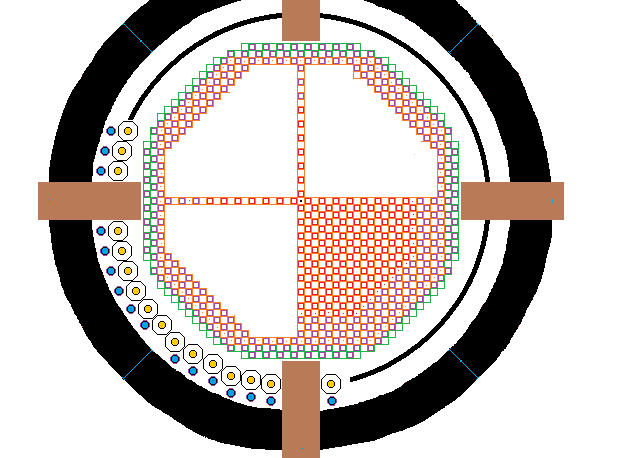
A FNR consists of central active fuel bundles surrounded by passive fuel bundles and cooling fuel bundles which in turn are surrounded by the FNR Skirt with its gadolinium layer and then a ~ 1.7 m wide liquid sodium guard band. Within the guard band are the 48 intermediate heat exchangers along the path shown as a solid black ring. The primary sodium pool walls are 2 m thick and are filled with fire brick. In the above diagram only one quadrant of fuel bundles is fully detailed.
The above diagram is to approximate scale. The active movable fuel bundles are shown in red. The passive fixed fuel bundles are shown in purple. The cooling bundles are shown in green. For structural stability the diagonal fuel bundle assembly faces are composed of fixed fuel bundles, except at 8 clipped corners. A 6 m high steel skirt covered on one side with gadolinium surrounds the assembly of fuel bundles at the same elevation as the fixed fuel bundles. The skirt has eight straight sections each of which is fastened to two 45 degree corner posts. The corner posts are fixed to the supporting open steel lattice.
FNR FUEL BUNDLE DIMENSIONS:
The external dimensions of the tubed portion of a movable fuel bundle including shroud thickness, fabrication tolerance allowance, thermal expansion allowance and swelling allowance are:
[19 X (5 / 8)] inches wide X [19 X (5 / 8)] inches long X 6 m tall. At the inner face of the shroud the dimensions of the tubed portion of the fuel bundle are:
[17 X (5 / 8)] inches wide X [17 X (5 / 8)] inches long X 6 m tall.
FUEL BUNDLE SWELLING ALLOWANCE:
Each movable fuel tube bundle has a (5 / 8) inch thick provision all the way around for the shroud thickness, fabrication tolerance allowance, thermal expansion allowance and swelling allowance. From the web page titled: FNR Fuel Bundle the shroud plate thickness is:
3 / 16 inch.
Hence, even with perfect movable fuel bundle fabrication, the maximum fuel bundle swelling allowance is:
{[2(5 / 8) inch - 2(3 / 16) inch] / 17 inch} X 100% = 5.14%
The significance of this permitted swelling fraction is that when the fuel bundle swelling in the core zone reaches 5% the fuel bundle must be reprocessed, regardless of its contained Pu or fission product fractions. Otherwise a movable fuel bundle could jam between its adjacent fixed fuel bundles.
FIXED FUEL BUNDLE MAXIMUM DIAGONAL LENGTH:
Neglecting the corner clips the maximum diagonal width of a fixed fuel bundle is given by:
23 X (5 / 8) inch X (2)^0.5 = 20.329 inch. A swelling of 5% increases this dimension to:
1.05 X 20.329 inch = 21.345 inch.
Hence the fuel bundle transfer airlock should be made from 24 inch OD steel pipe.
Each fuel bundle has an overall length of 8.0 m.
The maximum external dimensions of a fixed fuel bundle including shroud thickness, tolerance allowance and thermal expansion allowance are:
[23 X (5 / 8)] inches face to face X [23 X (5 / 8)] inches face to face X 6 m tall. The octagon allowances are formed by clipping off 2 fuel bundles off each corner of a 23 X (5 / 8) inch X 23 X (5 / 8) inch square.
In order to achieve both good liquid sodium natural circulation, which requires fuel tubes on a square grid, and good horizontal mechanical stability alternating smaller movable and larger fixed fuel bundles are used. The maximum face to face size allocation for the fixed fuel bundles is set at:
23 X (5 / 8) inch = 14.375 inches
by transportation weight constraints. The maximum dimensions of the movable fuel bundles are:
19 X (5 / 8) inch = 11.875 inches face to face.
These dimensions result in a linear center to center spacing of:
[14.375 inch + 11.875 inch = 26.25 inch
= 26.25 inch X .0254 m / inch = 0.66675 m.
This dimension is close enough to (2 / 3) m to permit a scale plan view diagram in m rather than inches.
The above diagram was prepared using a scale of:
14 squares = (2 / 3) m
On the above diagram the ratio of the small square size to the larger square size is not exactly correct but it is close enough for diagramatic purposes.
ASSEMBLY OF FUEL BUNDLES:
The fuel bundle geometry starts as a 45 X 45 square. The straight horizontal and vertical faces are each 21 bundles long. Hence each of the cut off corners of an isosoles triangle is:
(45 - 21) / 2 = 12
bundle positions to a side. Hence the number of movable fuel bundle positions in each cut off corner is:
12 + 10 + 8 + 6 + 4 + 2 = 42
and the number of fixed fuel bundle positions in each cut off corner is:
11 + 9 + 7 + 5 + 3 + 1 = 36
so the total number of cut off corner fuel bundle positions is:
42 + 36 = 78.
The result is an octagon. In addition two fixed and one movable fuel bundle are clipped of each of 8 octagon corners to avoid clashing with neighbouring intermediate heat exchange bundles.
Hence the total number of potential fuel bundle positions in the total fuel bundle array is:
45^2 - 4 (78) - 8(3) = 2025 - 312 - 24 = 1689 fuel bundle positions
A physical count shows that there are 464 active movable fuel bundles and 481 active fixed fuel bundles.
A physical count shows that there are:
4 X 57 = 228 cooling fuel bundle positions, of which 112 are for fixed fuel bundles and 116 are for movable fuel bundles.
Hence the number of passive fuel bundles is:
1689 - 464 - 481 - 228 = 516 passive fuel bundles.
The minimum number of times through cooling fuel bundle positions required to cool all the active fuel bundles is the larger of:
(464 M / 116 M) = 4.0
and
(481 F / 112 F) = 4.295
which imples at least 5 fuel bundle cooling cycles per fuel cycle.
Thus if the period of a fuel cycle is 30 years, there should be a planned reactor shutdown every 6 years for partial fuel bundle exchange and fuel bundle rearrangement.
To minimize the liquid sodium requirement the assembly of fuel bundles is chosen to be close to a regular octagon so that it will fit snugly within a cylindrical liquid sodium tank wall. Before octagon corner clipping the octagon straight faces consist of 11 octagonal fuel bundles separated by 10 square fuel bundles. The length of a straight side measured between the centers of the end bundles is:
10 X 42 X (5 / 8) inch = 262.5 inch.
Measured from the ends of these fuel bundles the straight face length is:
262.5 inch + 23(5 / 8) inch = 276.875 inch
The octagon angled faces each consist of 13 corner connected fixed fuel bundles. Straight and diagonal face fuel bundles are shared at corners.
Measured along a diagonal through fixed fuel bundles, the center to center distance between adjacent fixed fuel bundles is:
(2^0.5) X [21 X (5 / 8) inch]
= 18.561 inch
Measured from fixed fuel bundle center to fixed fuel bundle center the length of a diagonal face is:
12 X 18.561 inch
= 222.738 inch
which is less than would be the case for an ideal regular octagon.
The fuel bundles are a subset of a theoretial array 45 bundles X 45 bundles. There is a fixed bundle at each corner of the theoretical array and there is a fixed bundle at the center of the array.
Measured from fixed fuel bundle center to fixed fuel bundle center the horizontal face to horizontal face distance of the
entire assembly of fuel bundles is:
[44] X [(21 X (5 /8) inch] = 577.5 inch
Measured from the outside edges of the fixed fuel bundles the fuel bundle assembly horizontal face to horizontal face distance is:
577.5 inch + [23 X (5 /8) inch] = 591.875 inch
= 591.875 inch X .0254 m / inch
= 15.034 m
OPEN STEEL LATTICE:
The fuel bundles are supported by an open steel lattice. In order to make the open steel lattice components replaceable this lattice is composed of 30 slices, such that each slice supports 3 X (~ 1 / 2) lines of fuel bundles. Hence the width of each open steel lattice slice is:
15.034 m / 15 = 1.002267 m
The length 0f the longest ~ half slice is:
11 X [19 X (5 / 8) inch] + 12 X [23 X (5 / 8) inch]
= 130.625 inch + 172.5 inch
= 303.125 inch
= 7.699375 m
= 7.7 m
Hence to allow for tolerance issues the inside dimensions of the equipment transfer airlock must be greater than:
1.1 m X 1.6 m X 7.8 m
GUARD BAND WIDTH:
The intermediate heat exchange bundles are located at an elevation above the top of the fuel tubes, so that primary sodium guard band extends under the intermediate heat exchange bundles. The reactor primary sodium pool is 20 m inside diameter which provides a neutron absorbing guard band 1.8 m to 2.5 m thick around the perimeter of the fuel bundle assembly. The primary sodium pool liner and the heat exchange bundle supporting steel columns are further protected by a sheet gadolinium skirt. The heat exchange bundles are protected from neutrons originating in the core fuel via a very long diagonal path through the fuel blanket.
Note that the cost of the reactor enclosure roof and the reactor service gantry crane increase rapidly with increasing primary sodium pool diameter, so larger fuel bundle assembly diameters may be uneconomic.
From a structural component transportation perspective it is advantageous to keep most of the steel beams that support the reactor, its enclosure roof and the gantry crane less than 16 m long. Hence limit the face to face diameter of the assembly of fuel bundles to 15.034 m. This restriction allows the use of a liquid sodium pool that has an inside diameter of 20 m and a reactor building with an outside dimensions of 30 m X 30 m.
FUEL BUNDLE ASSEMBLY FACE TO FACE OUTSIDE DIMENSION CHECK:
[23 X 23 X (5 / 8) inch] + [22 X 19 X (5 / 8)inch]
= [(23 X 23) + (22 X 19)] X 5 / 8 inch
= (529 + 418) X (5 / 8) inch
= 539.375 inches
= 591.875 inch X 0.0254 m / inch
= 15.034 m
The corresponding radius is:
15.034 m / 2 = 7.517 m
FUEL BUNDLE ASSEMBLY MAXIMUM RADIUS BEFORE OCTAGON CORNER CLIPPING:
The maximum fuel bundle assembly radius is:
= {[(face to face diameter) / 2]^2 + [(face length) / 2]^2}^0.5
= {[(591.875 inch) / 2]^2 + [(276.875 inch) / 2]^2}^0.5
= {87,579.00 inch^2 + 19,164.94 inch^2}^0.5
= 326.717 inch
= 326.717 inch X .0254 m / inch = 8.2986 m
Thus, before octagon corner clipping the maximum available ring width for heat exchangers plus relative thermal expansion allowance is:
10.00 m - 8.30 m = 1.70 m
With octagon corner clipping this allowance increases to about 1.8 m.
INTERMEDIATE HEAT EXCHANGER RING WIDTH:
Around the perimeter of the fuel bundle array there must be ring of sufficient width for the intermediate heat exchangers. There is space for 56 heat exchangers in a single ring.
Each heat exchanger is 38 inches in diameter as set by perimeter pressure flange requirements. The outer manifold edge of the ring of heat exchangers is 0.6 m from the pool wall. Hence the ring of heat exchangers are on a circle with a radius of:
10 m - 0.6 m - 19 inch(0.0254 m / inch)
= 9.4 m - 0.426 m
= 8.974 m
~ 9.0 m
On this circle the ring of heat exchanges are spaced center to center at:
2 Pi (8.974 m) / 56 = 1.00688 m intervals
= 39.64 inch intervals.
Hence the minimum required primary sodium pool radial width taken up by the intermediate heat exchangers is:
0.6 m + 38 inch
= 0.6 m + .9652 m inch
= 1.565 m
PRIMARY SODIUM POOL DIAMETER:
Recall that the maximum fuel bundle assembly maximum radius is:
= [20 m - 2(1.7 m)] / 2 = 8.30 m
Thus the minimum required primary liquid sodium pool inside radius is:
8.30 m + 1.565 m
= 9.865 m
~ 10.0 m
so with reasonable construction tolerances the required primary sodium pool inside diameter is 20.00 m
FUEL BUNDLE GRID:
The reactor fuel bundle array is formed from a theoretical fuel bundle grid which has has 45 rows and 45 columns. The reactor diagonal faces are formed from octagonal fuel bundles.
The assembly of fuel bundles consists of a square main grid of 45 X 45 fuel bundles with:
(1 + 3 + 5 + 7 + 9 + 11)= 36 fixed fuel bundles cut off each corner and (2 + 4 + 6 + 8 + 10 + 12)= 42 mobile fuel bundles cut of each corner.
In addition there are 8 more fixed fuel bundles removed to ensure adequate intermediate heat exchanger clearance.
In addition there are 16 more movable fuel bundles removed to ensure adequate intermediate heat exchanger clearance.
The total number of fixed fuel bundle positions remaining in one such reactor is:
(23 X 23) + (22 X 22) - 4(36) - 8
= 529 + 484 - 144 - 8
= 861 fixed fuel bundles.
The total number of movable fuel bundle positions remaining in one such reactor is:
(23 X 22) + (22 X 23) - 4 (42) - 2(8)
= 1012 - 168 - 16
= 828 movable bundle positions.
Note that:
861 + 828 = 1689 bundle positions as expected.
Thus in summary one reactor contains 861 fixed fuel bundle positions and 828 movable fuel bundle positions for a total of 1689 fuel bundle positions.
COOLING ZONE:
At the outer edge of the fuel tube assembly are two rings of potential fuel bundle positions that are reserved for used fuel bundles that are cooling outside the neutron flux.
The fuel bundle assembly outer two cooling rings contain:
112 fixed fuel bundle positions and
116 movable fuel bundle positions
PERIMETER BLANKET:
Surrounding the active fuel bundles but inside the cooling rings is the perimeter blanket.
Assume that for good fuel breeding behind the fuel assembly straight octagon faces a fully populated perimeter blanket consists of 4 fuel bundle rings with a total width of:
4 X 21 X (5 /8) inch
= 52.5 inches
= 1.333 m
and over the diagonal surfaces the perimeter blanket consists of 3 fuel bundle rings with an effective width of:
3 X 21 inch X (5 / 8) inch X 2^0.5 = 55.684 inch
= 1.414 m
MANIPULATING COOLING FUEL BUNDLES:
Outside the fully populated rings of passive fuel bundles are 2 rings of cooling active fuel bundles. These two rings of fuel bundles do not have indicator tubes attached, but in terms of external dimensions the cooling active fuel bundles are the same as passive fuel bundles.
During normal reactor operation some of these cooling fuel bundle positions are left vacant to allow fuel bundle position flexibility for unscheduled maintenance. The maximum cooling bundle capacity is:
112 fixed bundles
plus
116 mobile bundles.
FUEL BUNDLE REPOSITIONING AND EXCHANGE:
1)The 1st step in fuel bundle exchange is to remove via the fuel bundle transfer air locks all of the cooling fuel bundles that are ready for reprocessing. This step is slow because the fuel bundles must drip off surface sodium before insertion into the airlock.
If there is any need for intermediate heat exchange bundle replacement this is the opportune time for this replacement.
2) The 2nd step is to disconnect relevant indicator tubes and to remove appropriate fixed fuel bundle corner bolts.
There are as many as:
(112 positions available for cooling fixed fuel bundles and up to 112 positions available for cooling movable fuel bundles. The indicator tubes need to be tenmporarily stored inside the primary sodium pool space. Thus there needs to be organized hangers and drip trays for this purpose. Note that the indicator tubes need to be interchangeable.
3) The 3rd step is to move:
228 used active fuel bundles from the fuel bundle assembly interior to the vacant cooling positions.
4) The 4th step is to extract the interior (1 / 3) of the blanket bundles for reprocessing via a fuel bundle transfer airlock. This step is slow because the fuel bundles must drip off sodium before insertioninto the airlock.
5) The 5th step is to move the middle third of the blanket bundles to the inner blanket bundle positions.
6) The 6th step is to move the outer third of the blanket bundles to the middle blanket positions.
7) The 7th step is to replace the 228 extracted active fuel bundles with new active fuel bundles brought in via a fuel bundle transfer air lock.
8) The 8th step is to repopulate the outer portion of the blanket with new passive fuel bundles brought in via the fuel bundle transfer airlock.
The above procedure is followed once every six years so that each lot of 228 active fuel bundles has six years to cool while immersed in liquid sodium prior to reprocessing and all the active fuel bundles are recycled once every 30 years. Every 6 years all the fuel bundles are repositioned so that over a 30 year period all the active fuel bundles receive approximately equal fast neutron exposure and all the passive fuel bundles receive approximately equal fast neutron exposure.
FUEL BUNDLE TRUCK TRANSPORT:
A fuel bundle is transported in a nearly horizontal position inside a shielded transport container mounted on a flat deck truck, with the top of the fuel bundle near the back of the truck. The transport container is slightly sloped so its lowest point is near the front of the truck. The fuel bundle and its transportation container are supported at an slight angle from horizontal to ensure that the fuel tubes remain overlapping their support grating.
The fuel bundle overall length and width are limited by the weight of the shielded container needed to safely move a radioactive fuel bundle along city streets by truck.
It is contemplated that the truck trailer will have 4 rear axels each with 4 of wheels so as to be rated for 4 axles X 4 wheels / axle X 5 tons per wheel = 80 tons at the rear of the truck triler. The truck tractor will have additional 2 load bearing axles each with 4 wheels as well as forward wheels for steering.
During truck transport crossing water every core fuel bundle must be surrounded by a transportation safety material (eg gadolinium compound) to prevent the fuel bundle becoming critical if the shielded transportation container is accidentally immersed in water.
This web page last updated
July 2, 2023.