| Home | Energy Physics | Nuclear Power | Electricity | Climate Change | Lighting Control | Contacts | Links |
|---|
INTRODUCTION:
Elsewhere on this website Fast Neutron Reactors (FNRs) have been identified as the primary source of energy for meeting mankind's future energy needs.
Nuclear reactors are normally located at stable sites. Actual peak ground acceleration (PGA) values that must be designed for vary by location.
EARTHQUAKE THREAT:
Earthquakes with peak ground acceleratios (PGA) of up to 3 g have been known to occur but are extremely rare. Peak horizontal ground accelerations of over 1.26 g seldom occur. Nuclear power stations are usually only built at sites where the Peak Ground Acceleration (PGA) is acceptable.
At existing Ontario nuclear power plants the PGA is typically 0.05 g;
In Ontario the PGA is generally less than 0.1 g;
In most major world population centers the PGA is usually less than 0.3 g;
Near fault lines in Japan, where earthquakies are frequent, the PGA may be as much as 0.5 g.
An issue with nuclear power plants (NPPs) is that typically half the total plant cost fits under the heading "Civil Work".
The civil work must conform to the location specific PGA value.
However, the cost of PGA conformance substantially increases with the PGA rating.
It was originally thought that a standardized NPP design ought to be rated for installation anywhere where the PGA is less than 0.3 g.
However, imposing a 0.3 g PGA conformance specification on a NPP located at a site with a maximum PGA of 0.1 g triggers unacceptable extra costs. Hence the concept of a standardized NPP design has proven to be unworkable.
For the NPP described herein, under sufficient sustained horizontal acceleration the sodium level on one side of the pool rises 1 m and then overflows onto the pool deck. This sodium overflow limits the maximum sodium pressure at the bottom of the sodium pool.
On the opposite side of the sodium pool the sodium level drops 1 m. The correponding slope of the sodium surface is:
2 m / 20 m = 0.1
Hence the corresponding maximum allowable PGA horizontal component is 0.1 g.
Increasing the FNR's PGA rating would require increasing the height of the sodium pool deck above the sodium surface. That in turn would increase the length of the intermediate heat exchange bundles, which in turn would increase the required airlock length. Further,to maintain the sodium pool deck elevation for fuel changes, the baseplate level would have to be reduced. Hence increasing the NPP PGA rating has a major impact on NPP design.
In addition to sodium sloshing about it is necessary to consider the horizontal forces caused by the inertia of heavy items such as steam generators, induction pumps and concrete walls.
Nuclear reactors are normally located at stable sites. Actual peak ground accelerations that must be designed for vary by location.
Ontario = 0.1 g;
Clinch River = 0.2 g
Export Requirement = 0.3 g
Extremely poor location = 0.5 g.
EARTHQUAKE SOLUTION:
The nuclear island rests on a reinforced concrete foundation baseplate 52 m diameter. Hence when there is an earthquake the entire nuclear island moves as a single unit with no relative motion between its various solid parts. The radial pipes between the nuclear island and the steam generators run through trenches that have enough space to allow earthquake induced pipe flexing.
The fuel assembly is located deep in the sodium pool. When the sodium pool is shaken there is violent surface wave motion but 6 m down the sodium moves with the pool walls so there is little relative motion between the sodium and the fuel assembly.
However, the intermediate heat exchange bundles are located near the liquid sodium surface, so they must be supported with violent sodium surface wave motion in mind. The intermediate heat exchange bundles must be able to move radially to accommodate +/- 0.2 m of connected NaK pipe thermal expansion and contraction.
To reduce earthquake induced hoop stress on the sodium pool walls the sodium is permitted to slosh around like water in a drinking glass.
In order to allow thermal expansion and contraction of the NaK pipes there is no rigid connection between the intermediate heat exchangers and the sodium pool liner. The reactor space enclosure walls above the sodium pool are attached to the pool deck. These walls are permitted to flex to maintain a gas seal while allowing for thermal expansion and contraction of the NaK piping. There is a small gap between the bottom of the reactor space enclosure side wall and the pool deck so that the wall can thermally expand with respect to the pool deck. This gap is gas sealed by a 26 m diameter flexible metal boot. The NaK pipe jackets are sealed to this wall by ceramic insulation and bellows fittings.
The thin control tubes going to the fuel bundle actuators must also be able to flex in Earthquake conditions.
VERTICAL ACCELERATION:
The FNR reactivity is controlled by relative vertical movement of adjacent fuel bundles. Hence the fuel assembly must be sufficiently rugged that an earthquake cannot induce relative fuel rod or fuel bundle movement geater than 1 mm.
An important potential limiting factor is earthquake induced vertical acceleration. The fuel rods are held in position in the fuel tubes by gravity. If an earthquake produces a sudden upward acceleration greater than gravity followed by an immediate 1 g of gravitational acceleration the fuel rods could rise in their fuel tubes. The fuel tubes are in essence fixed to the Open Steel Lattice. Vertical movement of the open steel lattice is damped by the liquid sodium pool. In this circumstance there is no certainty as to the relative positions of the movable and fixed fissile fuel rods, leading to potential for an accident. Thus any reactor site that can potentially produce an earthquake induced transient vertical acceleration greater than 1 g should be rejected.
EARTHQUAKE OVERVIEW:
Severe earthquakes can cause short term horizontal oscillating ground accelerations of up to 3 g, although 1.25 g is a more practical design limit. The design approach taken herein is to design the FNR fuel bundles to resist normal crane handling stresses and to mount the fuel bundles in a fuel assembly supported by an open steel lattice resting on the sodium pool bottom such that if a severe earthquake occurs the fuel assembly, the open steel lattice and the immediately surrounding liquid sodium all move together with the sodium pool walls and the surrounding ground.
During an earthquake the top surface of the liquid sodium will slosh around within the pool walls due to relative movement of the pool structure with respect to the liquid sodium. The 5 m high protected enclosure side walls will confine the liquid sodium for earthquake horizontal accelerations of up to 0.6 g.
The individual fuel tubes are protected from translational forces by the shroud plates and diagonal plates. However, on one side of the fuel assembly the shroud plates must exert force for vertical displacement the liquid sodium ahead of the fuel assembly.
The horizontal ground displacement during an earthquake can be expressed in the form:
(X - Xo) = A sin(W t)
Where;
Xo = initial horizontal position of the primary sodium pool with respect to the ground
X = primary sodium pool horizontal position as a function of time
A = maximum value of (X - Xo)
W = angular frequency of earthquake vibrations in radians / s
t = time
The velocity V is given by:
V = d(X - Xo) / dt
= W A cos(W t)
Hence the peak velocity Vp is given by:
Vp = W A
The horizontal ground acceleration Ah is given by:
Ah = dV / dt
= - W^2 A sin(W t)
= - [(W A)^2 / A] sin(W t)
Hence the peak horizontal ground acceleration Ahp is given by:
Ahp = [(W A)^2 / A]
Hence:
Ahp = Vp^2 / A
or
A = Vp^2 / Ahp
A violent earthquake is characterized by:
Ahp = 1.24 g
= 1.24 X 9.8 m / s^2
= 12.15 m / s^2
and by:
Vp = 1.16 m / s
Note that at a sustained 1.24 g horizontal acceleration the surface of the liquid sodium will be at more than 45 degrees to a horizontal reference.
Hence:
A = Vp^2 / Ahp
= [1.16 m / s]^2 / [12.15 m / s^2]
= 0.1107 m
which is a typical horizontal ground displacement.
Recall that:
W = Vp / A
or
F = Vp / (2 Pi A)
= (1.16 m / s) / [6.28 (0.1107 m)]
= 1.67 Hz
The liquid drag force F is given by:
F = K V^2
Thus the peak drag force Fp is given by:
Fp = K (W A)^2
Thus the intermediate heat exchanger bundles must be sufficiently robust to withstand a transverse liquid sodium flow rate of 1.16 m / s.
Thus in terms of drag force on the fuel assembly and intermediate heat exchange bundles we are concerned about the maximum horizontal ground velocity. The intermediate heat exchange bundles may need wound wire spacers to limit the potential sheer force on individual heat exchange tubes.
POTENTIAL STANDING WAVES:
It is possible that there might be an issue with the natural surface wave resonant frequency of a 20 m diameter pool being excited by the earthquake frequency. The pool could be considered to be like a U tube where if the liquid rises on one side it falls on the other side. This system is in some respects like a pendulum. There is a kinetic energy associated with the liquid sodium moving up and down. There is potential energy associated with the sodium on one side of the pool being higher than the other side. A large slosh corresponds to a pendulum radius of 10 m. Smaller sloshes correspond to larger pendulum radii.
PENDULUM ANALYSIS:
Define:
Rp = pendulum length
Theta = pendulum angular deviation from vertical.
Pendulum KE = M V^2 / 2
= (M / 2) (Rp d(Theta) / dt)^2
H = fuel assembly center of mass height above its height when the pendulum is upright.
For small angles:
Pendulum PE = M g H = M g Rp Theta^2
Total Energy
= TE = KE + PE
= (M / 2) [Rp d(Theta) / dt]^2 + M g Rp Theta^2
= (M Rp / 2) [Rp (d(Theta) / dt)^2) + 2 g |Theta|]
Theta = B sin(Wp t)
Theta^2 = B^2 sin^2(Wp t)
dTheta / dt = B Wp cos (Wp t)
(d(Theta) / dt)^2 = B^2 Wp^2 cos^2(Wp t)
giving:
TE = (M Rp / 2) [Rp (d(Theta) / dt)^2) + 2 g Theta^2]
= (M Rp / 2) [Rp B^2 Wp^2 cos^2(Wp t) + 2 g B^2 sin^2(Wp t)]
= (M Rp / 2) B^2 2 g [(Rp Wp^2 / 2 g) cos^2(Wp t) + sin^2(Wp t)
]
= constant
Recall identity that:
cos^2(Wp t) + sin^2(Wp t) = 1
Hence:
Rp Wp^2 / 2 g = 1
or
Wp = [2 g / Rp]^0.5
or
Fp = (1 / 2 Pi)[2 g / Rp]^0.5
CAVITY RESONANT FREQUENCY RANGE:
For Rp = 20 m:
Fp = (1 / 2 Pi)[2 g / Rp]^0.5
= (1 / 6.28)[2 (9.8 m /s^2) / 20 m]^0.5
= 0.1576 Hz
For Rp = 10 m:
Fp = (1 / 2 Pi)[2 g / Rp]^0.5
= (1 / 6.28)[2 (9.8 m /s^2) / 10 m]^0.5
= 0.223 Hz
For Rp = 5 m:
Fp = (1 / 2 Pi)[2 g / Rp]^0.5
= (1 / 6.28)[2 (9.8 m /s^2) / 5 m]^0.5
= 0.315 Hz
Note that for severe earthquakes the cavity resonant frequency is much less than the earthquarke frequency. At low intensity earthquakes, where the earthquake frequency may be lower and periodic, we rely on the fuel bundles and the intermediate heat exchangers to provide sufficient primary sodium flow damping to prevent earthquake excited surface waves in the liquid sodium from growing.
Note that the sodium pool will not support large waves at Rp > 10 m.
The FNR design set out herein must safely withstand a maximum horizontal ground velocity of 1.16 m / s.
EARTHQUAKE TOLERANCE:
FNRs must not be damaged by horizontal accelerations of up to 4.9 m / s^2 (0.5 g) and must not go prompt critical under the circumstances of the most violent recorded earthquakes involving horizontal ground shaking with accelerations up to 28 m / s^2 (3 g) and horizontal velocities up to 1.2 m / s. This level of earthquake tolerance can be achieved by supporting the fuel assembly and open steel lattice such that the liquid sodium inertia attenuates sheer force on the fuel assembly and the sodium level at the active fuel tubes never falls below the top of the active fuel rods.
A 1.0 g horizontl acceleration will cause the liquid sodium level on one sideof the sodium pool to drop by about 10 m. Thus there is 5 m of sodium remaining at the lowest point and about 10 m of sodium at the active fuel tubes. That is sufficient for keeping the active fuel rods immersed in liquid sodium.
When an earthquake wave is detected all the movable fuel bundles should immediately withdraw to reduce the reactor reactivity. The earthquake induced sodium wave might be sufficient to cause a mechanical distortion in whch case it is essential that the movable fuel bundles be fully withdrawn at the time the distortion occurs.
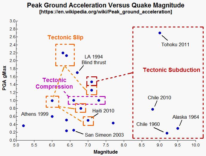
Here is a chart plotted by Dr. Alex Cannara of major recorded earthquakes.
With respect to reactor flexing in an earthquake one must think about reactor reactivity. If a reactor flexes away from its normal steady state geometry there must be certainty that the reactivity will decrease, regardless of the direction of flexing. If that is not the case, during a severe earthquake the reactor could briefly flex into a prompt critical state. In a U-235 fuelled thermal neutron reactor brief flexing into prompt criticality is not the end of the world because the flexing period is usually less than one second, so the time in prompt criticality is usually not sufficient for a large growth in the number of neutrons, provided that formation of coolant voids does not inject positive reactivity.
However, in a Pu-239 fueled fast neutron reactor the margin between normal and prompt critical is only about one third that in a thermal neutron reactor and the rate of growth of neutrons in a prompt critical state is two orders of magnitude faster in a FNR than in a thermal neutron reactor. Thus it is important to prevent fuel assembly flexing and as a backup there should be another mechanism to rapidly suppress prompt criticality.
There are two other stability mechanisms. One involves making the reactor short term power stable on fast neutrons independent of delayed neutrons. This is possible because the fuel temperature responds to prompt criticality faster than do the temperatures of the surrounding steel and sodium. The other involves linear fuel disassembly within fuel tubes which disassembly must operate within about 10^-4 seconds. ie The mechanical dynamics of separation of core fuel rods inside a fuel tube must be comparable to the dynamics of a bullet in a gun.
Ideally a fast neutron power reactor should be stabilized by all three mechanisms.
A fourth important mechanism is to give the FNR sufficient thermal mass that it can withstand a brief period of prompt criticality.
One of the possible issues with a sodium cooled reactor is positive reactivity injection by a sodium thermal expansion and ultimately sodium voids. We need to keep the reactor in a regime where sodium void formation is impossible. That may require a deeper sodium pool to maintain a sodium pressure head than would otherwise be necessary.
This web page last updated Septeber 12, 2024.
| Home | Energy Physics | Nuclear Power | Electricity | Climate Change | Lighting Control | Contacts | Links |
|---|