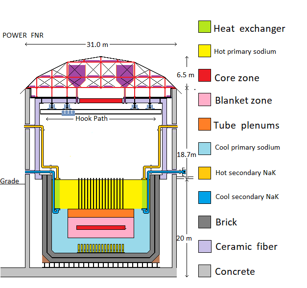
For diagramatic simplicity, in the above diagram the air locks, the open steel lattice supporting the fuel bundles and the steel columns supporting the intermediate heat exchange bundles are not shown.
| Home | Energy Physics | Nuclear Power | Electricity | Climate Change | Lighting Control | Contacts | Links |
|---|
INTRODUCTION:
Elsewhere on this website Fast Neutron Reactors (FNRs) have been identified as the primary source of energy for meeting mankind's future energy needs. This web page focuses on the design of an FNR's dome shaped roof and its related internal protective structure.
GENERAL APPROACH:
The general approach is for the FNR to have robust multi-layer concrete walls and a rigid dome roof under which is a layered protective structure. The concrete walls absorb low angle falling missile attacks, the dome shape deflects low angle rising missile attacks and the internal structure and material used for fire suppression cause most of the kinetic energy and forces from high angle attacks to be widely distributed. The dome has sufficient average weight per unit area to withstand the maximum lifting forces induced by a tornado.
The external radius of the dome is constant permitting a rapid temporary external roof repair by repositioning a preformed curved steel sheet that is stored on the top center of the dome.
The air space under the dome is isolated such that if a temporary roof repair is made after a roof penetrating missile or bomb attack a hot sodium pool fire can be asphyxiated.
The dome has a constant curvature to allow a patch to be applied anywhere on the dome surface.
FAST NEUTRON REACTOR SIDE ELEVATION:
For diagramatic simplicity, in the above diagram the air locks, the open steel lattice supporting the fuel bundles and the steel columns supporting the intermediate heat exchange bundles are not shown.
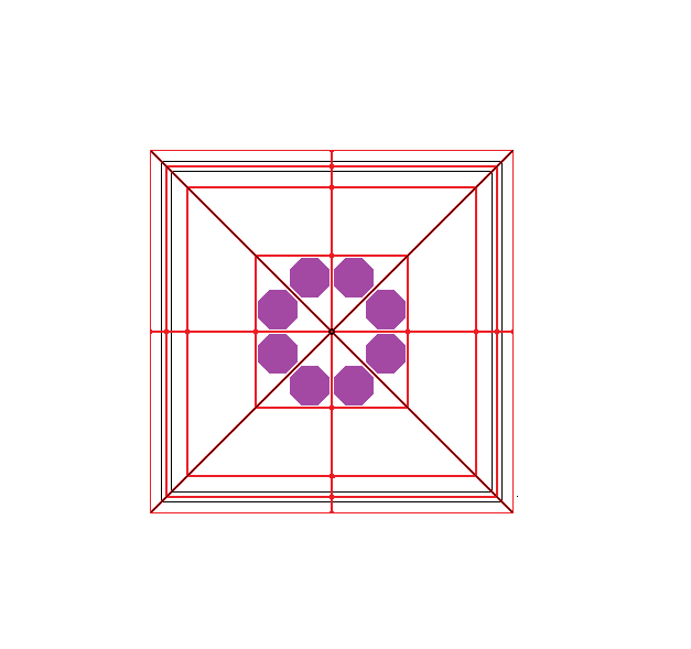
FNR DOME PLAN VIEW:
The following diagram shows a plan view of the FNR
dome. The structural steel frame members are shown in red. The NaCl reservoirs are shown in purple. The top of the supporting concrete side wall is shown in black.
FNR Dome dimensions in Plan View:
a)The outside dimensions of the FNR Dome roof are 33 m X 33 m.
b) The outside dimensions of the supporting concrete wall are 31 m X 31 m.
c) The inside dimensions of the supporting concrete side wall are 29 m X 29 m.
d) In plan view the apparent width of the lower roof section having a 45 degree slope is 2.4 m.
e) In plan view the apparent width of the middle roof section having a 27 degree slope is 6.2 m.
f) In plan view the apparent width of the top roof section with slope of 9 degrees is 6.9 m.
Note that:
6.9 m + 6.2 m + 2.4 m = 15.5 m = half the outside distance between two parallel concrete walls.
DOME FUNCTIONS:
The FNR Dome provides a combination of structural, weather protective, missile protective, fire suppression, emergency air exclusion and emergency water exclusion functions.
The structural functions include:
a) Support of the sodium pool space side walls;
b) Support of the sodium pool space ceiling;
c) Support of the overhead monitoring system;
d) Support of the overhead gantry crane;
e) Support eight reservoirs containing a total of 300 tonnes to 600 tonnes of NaCl / Na2CO3 / MgCO3 fire suppression material;
f) Support of a steel structure of sufficient strength to withstand the air coupled nearby explosive blast of a bomb;
g) Provision of a bottom section interior to the side wall that will provide roof lateral stability in a hurricane;
h) Support of the outer water seal protective surface;
i) Horizontal tie bars of sufficient strength to cancel out edge radial forces;
j) Vertical hangers positioned to support the various loads;
k) A central vertical rod to stabilize the dome top center and dome bottom center.
l) Support of numerous polyester energy absorbing nets.
m) Air tight roof space access doors to permit asphyxiation of a sodium fire.
The weather protective functions include:
a) A water tight membrane with UV top surface protection;
b) A membrane support surface with sufficient slope for natuaral drainage;
c) Sufficient surface rigidity for shape maintenance in a hurricane;
d) Sufficient distributed weight to withstand a tornado;
e) Sufficient lateral support to withstand either a hurricane or a severe earthquake;
f) Integral missile protection sufficient to withstand impacts by tree trunks or utility poles thrown by hurricane or tornado winds. Note that wind blown missiles generally have impact velocites less than 100 m / s, are generally less dense than solid steel and typically have averarge densities comparable to water.
It is likely impossible for a FNR power plant to absorb a determined military attack without incurring some damage. Hence, in the event of a determined military attack the object is to prevent a major FNR prompt neutron critical explosion or a major unsuppressed sodium fire, not to expect the FNR to be operable soon after such an attack.
MILITARY ATTACK:
Practical experience during the Russian invasion of Ukraine has demonstrated that an irrational high altitude military attack with a laser guided armor piercing bomb may become a credible future threat to some FNRs. This irrational military threat issue is shared by other types of nuclear power plants and by major hydro-electric dams.
It is impossible to design a power plant that can continue safe operation during and immediately after a determined military attack. However, it is possible to design a nuclear power plant so that the consequences to the public, other than loss of power plant capacity, are minimal. In the case of a FNR one of the design objectives is to make it impossible for a single military projectile to cause either a major prompt neutron critical explosion or a major unsuppressed primary sodium fire.
Military Missile Protection:
The FNR military missile protective functions include:
a) Ability to resist low angle attacks such as an impact by a descending airplane or a direct attack by an artillery shell or an anti-tank (shaped charge) projectile;
b) Ability to resist a high angle attack such as an impact by a falling artillery shell or a falling anti-tank bomb;
c) Ability to resist a high angle attack with an armor piercing bomb dropped from a high altitide;
d) Ability to resist a high angle attack by a ballistic rocket with a warhead that explodes on impact.
ARMOR PIERCING BOMB:
A six ton armor piercing bomb typically consists of a tall thin bomb casing with a hard pointed nose made from about 3 tons of tungsten carbide, tail fins that modify the falling bomb trajectory to home on a laser designator and the balance of the bomb weight consisting of nearly 3 tons of stable explosive. The bomb is typically dropped from an altitide of about 15,000 feet and attains an impact velocity greater than the speed of sound. The hard pointed nose allows it to pierce through thick mild steel armor or through a 5 m thickness of reinforced concrete. The bomb has a time delay fuse which causes detonation of the explosive after the bomb has fully penetrated its target. During WWII this type of bomb, without laser guidance, was succesfully used to attack deep railway tunnels, the German U-boat pens and to sink the heavily armored German battleship Tirpitz.
It is impractical to build a rigid dome over a FNR that can withstand an attack by such an armor piercing bomb. However, it is possible to design a reactor dome that will minimize the consequences to the surrounding public of such an attack. The dome must incorporate an internally layered protective structure consisting of:
a) A firm watertight outside surface that will cause a contact munition to explode outside the dome, thus causing the explosive energy to dissipate over a wide area.
b) Internal layers that can distribute the initial point impact force over a larger area and that will trigger any remaining unexploded contact munitions;
c) Multiple layers of tightly stretched woven polyester bags containing rigid expanded polystyrene fill configured to distribute as much of the bomb's kinetic energy over the widest possible area of the dome. There are about 200 m^2 of these bags piled 0.3 m deep.
d) If the bomb penetrates through the polyester covered bags and into the primary sodium pool space the powdered NaCl/MgCO3 in four reservoirs will flow down to cover te exposed liquid Na surface. At temperatures between 350 C and 900 C MgCO3 spontaneously emits CO2 which will form bubbles in the NaCl crust which isolates the primary sodium from air in the space while heat is being extracted from the primary sodium.
DOME GEOMETRY:
Assume that the dome upper surface is part of an ideal sphere. Assume that the slope of the dome upper surface at its outside radius is 45 degrees. Then a bit of geometry shows that the ratio of dome height to dome diameter for an ideal sphere is: 0.2071.
Hence,if in plan view the dome outside diameter is 31 m to the outer edge of the supporting concrete side walls then the theoretical dome height above the top of the side walls is:
0.2071 (31 m) = 6.42 m
The inside structure of the dome should extend at least 1 m below the top of the concrete side walls to provide the dome lateral stability.
To allow for shedding of rainwater the outer edges of the dome should extend about 1 m beyond the outside of the supporting concrete side walls. Hence in plan view the dome will appear to have a diameter of 33 m.
DOME STRUCTURE:
The dome is defined by a structural steel I beam frame consisting of radial sloped rafters, horizontal radial tie bars and horizontal perimeter bars. There are vertical weight bearing hangers that operate in tension. The dome has a steel cable net top surface bolted to the I beam rafters on top of which the rigid roofing surface material is attached. A total of 224 internal diagonal bracing bars give the dome structure rigidity.
The steel cable net surface on top of the structural steel frame should assist in distribution of point impact forces.
The dome surface has a top central ring of 8 triangular faces, each of which is at 9 degrees to the horizontal. Then there is a middle ring of 8 faces, each of which is at:
9 degrees + 18 degrees = 27 degrees to the horizontal.
Then there is a lower ring of 8 faces, each of which is at:
27 degrees + 18 degrees = 45 degrees to the horizontal.
Radial forces from the rafters in compression are balanced by the horizontal tie bars that normally operate in tension. In addition there are four sets of circumferential bars that normally operate in tension. There is a central vertical pole.
PROTECTIVE POLYESTER NETS:
Woven polyester bags stretched around expanded polystyrene forms are stacked on top of the horizontal tie bars to form up to 200 m^2 of protective nets. These nets have the property that when the net is deformed by a projectile point impact much of the projectile's momentum and kinetic energy are absorbed by the stretching of net material and compressing its backing polystyrene. The result is that the projectile energy and momentum are smoothly transferred onto the horizontal tie bars over a wide area, then to the dome and its supporting concrete sidewalls.
The top surface of the dome should consist of a water proof membrane underneath which are ceramic tiles epoxy bonded onto perforated steel plates. The ceramic tiles provide a hard layer which resists point penetration by a hard projectile nose material such as tungsten carbide. The steel plate perforations enhance the epoxy bond. The backing steel layer enlarges the area of the steel cable net over which the initial point impact force is distributed and provides welded back threaded rods for attaching these plates to the underlying steel cable net.
The steel cable net is bolted onto the top flange of the I beam rafters using flat head bolts. These bolts pass through metal strips which are the same thickness as the ceramic covered top plates so as to realize a nearly smooth top surface to which the waterproof membrane is applied.
The individual cable net strands must be of sufficient thickness to withstand the forces on them in a severe tornado.
If the dome surface is penetrated the underlying polyester bags containing expanded polystyrene further distribute the impact force over an even larger dome area.
GROSS WEIGHTS:
The dome and its fixtures must have sufficient weight to prevent it lifting during a tornado.
The minimum total roof weight per unit area must cancel a lifting pressure in a severe tornado of about:
0.2 X 101,000 Pa = 20,200 Pa
Dome plan area for tornado resistance:
Ad = (31 m)^2
= 961 m^2
Hence minimum total roof mass:
Mr = 2061 kg / m^2 X 961 m^2
= 1980621 kg
= 1981 tonnes
If the pool space side walls and ceiling have half the density of water their weight is about:
(1500 m^3 + 625 m^3) X 0.5 tonnes / m^3 = 1062.5 tonnes.
Ths NaCl in the reservoirs weighs over 800 tonnes.
The gantry crane rails and cross beam will collectively weigh about:
5 X 20 tonnes = 100 tonnes
The maximum available primary pool volume without sodium overflow is:
Pi (10 m)^2 (1 m) = 314.1 m^3
The maximum density of NaCl is about:
2.16 g /cm^3
Hence the maximum possible weight of NaCl in roof mounted reservoirs without pool overflow is:
2.16 X 10^3 kg / m^3 X 314.1 m^3 = 678 X 10^3 kg
= 678 tonnes
If the NaCl is stored in granular form its average density in the storage reservoirs will be about:
2.16 gm / cm^3 / 2 = 1.08 gm / cm^3 = 1.08 X 10^3 kg / m^3
The plan is to store the fire suppressing NaCl in 8 pseudo cones with top extensions, each 1.8 m high X 3.6 m in diameter. These cones provide certain controlled discharge. The volume of each pseudo cone is:
Integral from H = 0 to H = 1.8 m of:
([2 H]^2 - 2 [10 H / 18]^2) dH
= [4 - (50 / 81)] H^3 / 3
= [(324 - 50) /(243)] [1.8]^3 m^3
= 6.576 m^3
On top of each pseudocone is a straight vertical extension with a cross secional area of:
[3.6 m]^2 - 4 [1 / 2] m^2 = 10.96 m^2
After allowing for head room in the bottom section of the dome the available straight section height is:
3.1 m
Hence the available straight section volume is:
10.96 m^2 X 3.1 m = 33.976 m^3
Hence each NaCl reservoir holds:
33.976 m^3 + 6.576 m^3 = 40.552 m^3
Hence the total volume of the 8 NaCl fire suppression reservoirs is:
8 X 40.552 m^3 = 324.416 m^3
This amount is close to the theoretical 314 m^3 necessary to fill the primary sodium pool to the point of overflowing.
Then the mass of the NaCl in dome storage reservoirs will be about: 324.416 m^3 X 1.08 kg / m^3 = 350.4 tonnes
If the FNR primary sodium pool is hit by a penetrating projectile this granular NaCl should pour down onto the primary sodium pool to exclude air while the primary Na pool is being cooled.
DOME GEOMETRIC DETAIL:
The dome surface is composed of flat sections that approximate a portion of a sphere. The upper section has radial ribs of length L that are at 9 degrees to the horizontal plane. the middle section has radial ribs of length L that are at 27 degrees to the horizontal plane. The bottom section has radial ribs of length (L / 2) which are at 45 degrees to the horizontal plane.
In plan view the apparent length of the top section radial rafters is:
L cos(9 degrees) = L cos(Pi / 20)
In plan view the apparent length of the middle section radial rafters is:
L cos(27 degrees) = L cos(3 Pi / 20)
In plan view the apparent length of the lower section radial rafters excluding the outside overhang is:
(L / 2) cos(45 degree) = (L / 2) cos(Pi / 4)
Thus in plan view the apparent dome half width exclusive of the rain shedding overhang is:
L [cos(Pi / 20) + cos(3 Pi / 20) + (1 / 2) cos(Pi / 4)] = 15.5 m
L[0.9877 + 0.8910 + 0.3536] = L [2.2323] = 15.5 m
L = 15.5 m / 2.2323 = 6.9435 m
Hence on the plan view drawing:
L (0.9877) = 6.858 m ~ 6.9 m
L (0.8910) = 6.1866 m ~ 6.2 m
L (0.3536 m) = 2.455 m ~ 2.4 m
On the drawings this amount is:
6.9 m + 6.2 m + 2.4 m = 15.5 m
On the side elevation drawing the rise / run for each section is:
Lower section = tan(Pi / 4) = 1.0 = 1 / 1
Middle section = tan(3 Pi / 20) = 0.50952 ~ 1 / 2
Top section = tan(Pi / 20) = 0.1583 ~ 0.1666 = 1 / 6
TORNADO PROTECTION:
A typical tornado causes a local air pressure drop of:
0.1 X 101 kPa.
An extreme tornado causes a local air pressure drop of up to:
0.2 X 101 kPa.
The maximum roof area subject to a tornado induced air pressure drop is:
31 m X 31 m = 961 m^2
Let Mr - mass of roof structure including primary pool space side walls and ceiling, the gantry crane, the fire suppressent and the dome. Hence for the weight of the roof structure to be sufficient to balance the extreme tornado roof lifting force:
Mr g = 961 m^2 X 0.2 X 101,000 Pa
or
Mr = 961 m^2 X 0.2 X 101,000 Pa / (9.8 m / s^2)
= 1,980,837 kg
= 1,981 tonnes
This is the minimum total roof mass for roof stability in an extreme tornado.
Note that the hangers from the roof must be capable of supporting most of this weight.
the maximum working stress for steel is 10,000 lbs / inch^2. In metric units this is:
(10,000 / 14.7) X 101 kPa = 68.707 MPa
Hence the minimum total cross sectional area Ah of the roof hangers is:
Ah 68.707 MPa = Mr g
or
Ah = Mr g / (68.707 X 10^6 Pa)
= 961 m^2 X0.2 X 101,000 Pa / (68.707 X 10^6 Pa)
= 961 X 0.2 X .101 m^2 / 68.707
= 0.283 m^2
This hanger cross sectional area is divided over 24 hangers for an average of:
0.283 m^2 / 24 = 0.01179 m^2 / hanger.
Thus the hangers could be box beams 0.2 m X 0.2 m X .015 m wall. The cross sectional area of such abeam is about:
4 X 0.2 m X .015 m = .012 m
Note that this hanger cross sectional area will be reduced due to the weight of the roof surface material which is not borne by the hangers even in an extreme tornado.However, clearly the central pole must be much larger in cross sectional area than the average hanger
Under normal circumstances the weight (Mr g) is borne by the concrete perimeter wall which has a top surface cross sectional area of:
(31 m)^2 - (29 m)^2 = 961 m^2 - 841 m^2
= 120 m^2
Hence in normal circumstances the minimum normal downward average pressure on the perimeter wall is:
Mr g / 120 m^2
= (961 m^2 X 0.2 X 101,000 Pa) / 120 m^2
= 1.6 X 101 kPa
If the steel sill beam is only 0.4 m wide, this pressure on the concrete top surface increases to:
(1 / 0.4) X 1.6 X 101 kPa = 4.0 X 101 kPa
This web page last updated May 15, 2023.
| Home | Energy Physics | Nuclear Power | Electricity | Climate Change | Lighting Control | Contacts | Links |
|---|