| Home | Energy Physics | Nuclear Power | Electricity | Climate Change | Lighting Control | Contacts | Links |
|---|
INTRODUCTION:
The insertion depth of the movable fuel bundles into the matrix of fixed fuel bundles sets the fuel temperature at which the reactivity is zero, which is the average fuel temperature. The main function of FNR Actutors is to occasionally adjust the length of insertion or withdrawal of movable fuel bundles into the matrix of fixed fuel bundles to compensate for fuel aging or to temporarily reduce the reactor operating temperature as is necessary to enable fuel bundle shuffling or intermediate heat exchange bundle replacement.
When the FNR Actuators are stationary the FNR average fuel temperature is regulated by thermal expansion/contraction of the FNR fuel assembly.
Each FNR actuator is selectively addressable. Thus, in the event of a fuel tube rupture in a particular fuel bundle, it is possible to selectively shut down the fission reaction at that point in the fuel assembly while otherwise keeping the reactor operating.
Linear thermal expansion of steel is typically about 10 ppm / degree C to 16 ppm / degree C. If the fuel temperature setpoint is being regulated to within +/-10 degrees C and if the core zone diameter is typically 10 m then the fractional core zone area change due to thermal expansion at the setpoint temperature is about:
2 X (+/-10 degrees C) X 10 X 10^-6 / deg C = +/- 2.0 X 10^-4
Hence for a 0.5 m core zone length the play, hysterisis and position error of the actuator must be comparable to:
2 X 10^-4 X 0.5 m = 0.1 mm.
The insertion depth of each movable fuel bundle into the matrix of fixed fuel bundles is monitored using a ceiling mounted laser scanner, similar in operation to a laser measuring tape. This distance measurement to the top of an indicator tube establishes the actual movable fuel bundle insertion depth. Any deviation of the movable fuel bundle's actual insertion depth from its set point causes the FNR actuator to move the fuel bundle toward the insertion depth setpoint.
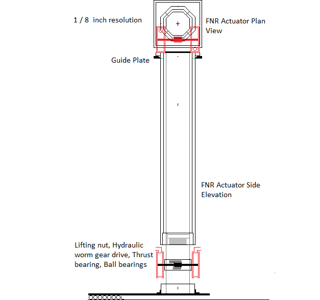
A FNR Actuator is a constantly loaded hydraulic piston that raises or lowers a movable fuel bundle over a range of 1.0 m for controlling the insertion of that movable fuel bundle into the matrix of fixed fuel bundles. This insertion must be precise, smooth and hysterisis free. The weight of the movable fuel bundle less its buoyancy force in liquid sodium and less the buoyancy force caused by its Indicator Tube is constantly acting downwards on the piston type actuator. That force is balanced by the liquid sodium pressure in the actuator cylinder and the actuator piston cross sectional area. The mass of a FNR movable fuel bundle is about 1.7 tonnes. A hysterisis free vertical position resolution of about:
0.1 mm = 100um
is desired.
The actuator consists of two vertical pipes, one which loosely slides inside the other. The bottom of the larger pipe is sealed closed except for the connection of the hydraulic fluid tube. The bottom of the inner pipe, which is the fuel bundle probe, is closed with a cap and piston ring. The top of this pipe has four radial fins for attachment to the downward projecting legs of a movable fuel bundle. Increasing the hydraulic fluid volume under the piston raises the movable fuel bundle. Lowering the hydraulic fluid volume under the piston lowers the movable fuel bundle. The hydraulic fluid volume under each piston is set by a valve that can inject more hydraulic fluid, isolate the contained hydraulic fluid volume in the piston cylinder or drain the hydraulic fluid to the sodium pool
On loss of house power the control valve defaults to draining the hydraulic fluid, causing the movable fuel bundles to retract.
The FNR actuator outer pipe has an OD of 8.625 inch, an ID of 6.875 inch and a wall thickness of 0.875 inch.(Schedule xx)
The FNR actuator inner pipe (The fuel bundle support pipe) has an OD of 6.625 inch, an ID of 4.897 inch and a wall thickness of 0.864 inch.(Schedule XX)
The required piston OD is 6.875 inch. Use a compressible piston where the weight of the movable fuel bundle causes the piston to expand to seal the piston perimeter with the ID of the larger pipe.
The piston cross sectional area is:
Pi (6.875 inch)^2 / 4 = 37.122 inch^2
= 0.02395 m^2
The desired resolvable change in trapped fluid volume is:
0.02395 m^2 X 10^-4 m
= 2.395 X 10^-6 m^3
= 2.395 cm^3
which is the minimum required volume resolution of the liquid sodium hydraulic fluid control valves.
At the top of the inner pipe are vertical fins that connect the inner pipe to the projecting bottom corner legs of the movable fuel bundle.
The sodium hydraulic fluid pressure required to lift the movable fuel bundle in the absence of buoyancy force is given by:
[1.7 tonnes x 1000 kg / tonne X 9.8 m / s^2] / [0.02395 m^2]
= 695.6 kPa
= 6.887 atmospheres
= 101.2 psi.
Both the inner and outer pipe must be firmly mounted to resist high bending torque
Simple thermal expansion of a fuel rod over 5 deg C is about:
(20 X 10^-6 / deg C) x 5 deg C X 300 mm = 0.03 mm
The amount of movable fuel bundle insertion must be constantly monitored. If the insertion depth signal is lost even briefly the movable fuel bundle must be withdrawn, which is the default condition.
Each sodium hydraulic pressure line should be fitted with a rupture disk. If a large weight falls on the corresponding indictor tube the rupture disk will fail causing withdrawal of the affected movable fuel bundle.
A feature of this arrangement is simplicity and a single control tube per movable fuel bundle.
The reactor setpoint temperature is controlled by the amount of movable fuel bundle insertion into the matrix of fixed fuel bundles. This insertion is a function of the difference in length between the FNR actuator and the adjacent fixed fuel bundle supports. The fixed fuel bundle supports are nominqlly 2.75 m high.
Earthquake induced changes to in the insertion of movable fuel bundles into the matrix of fixed fuel bundles must be kept less than 1 mm to prevent an earthquake from initiating a prompt neutron critical event causing sodium void instability.
To obtain the required bending resistance of the fuel bundle support pipes choose a movable fuel bundle probe which has an OD of 6.625 inch and a wall thickness of 0.864 inch.
The open area potentially available around the outside of this pipe is:
[17 X (9 / 16) inch]^2 - Pi [6.625 inch / 2]^2 - 12 [(9 / 16) inch]^2 - 4 (0.5 inch) (1.41) (1.47 inch)
= 91.44 inch^2 - 34.47 inch^2 - 3.797 inch^2 - 4.1454 inch^2
= 49.03 inch^2
Hence the 6.625 inch OD pipe cross section should not significantly impede the vertical sodium flow provided that sodium can flow laterally over the top of the movable fuel bundle support pipe.
The actuators and fixed fuel bundle support pipes are stabilized by the open steel lattice. This lattice contains 8.625 inch diameter holes on a square lattice that is:
42 (9 / 16 ) inch / 2 = 11.8125 inch center to center.
The gap between adjacent 8.625 inch pipes is:
11.8125 inch - 8.625 inch = 3.1875 inch
Each gap space is 2 m to 3 m high.
The core region has a perimeter of about 31 m. Hence the sodium flow cross section at the perimeter of the core zone is:Clearly we cannot make the core region diameter any bigger with these dimensions.
The open steel lattice has a clearance hole that stabilizes the top of the retracted support pipe ~ 1.5 m above the bottom of the open steel lattice.
The entry area for sodium flowing over the top of the movable fuel bundle support pipe is:
Pi (6.625 inch) D
where D is the minimum axial distance between the top of the support pipe and the bottom of the grating. In order to maintain the same cross sectional area for sodium flow:
[Pi (6.625 inch) D] / [Pi (6.625 inch / 2)^2]
= 4 D /6.625 inch
which indicates that for flow area maintenance:
D > 1.66 inch
The fractional open area is:
{[9 / 16)inch]^2 - Pi {(3 / 16)inch]^2 / [(9 / 16) inch]^2
= (81 - 9 Pi) / 81
= 0.651
For certainty we should make this gap between the support pipe and the grating at least 2.0inches.
Changing the sodium hydraulic pressure causes the inner pipe to move up and down over a height range of about 1.1 m. The 6.625 inch OD, round movable fuel bundle support pipe slides loosely inside the outer cylinder pipe.
The rupture disc is chosen so that it will fail if the vertical force becomes too large, as in a vertical impact to the FNR fuel assembly that might affect its relative fuel geometry. Such an impact might result from a ground penetrating bomb dropped from a high altitude.
When the rupture disc fails gravity will cause the movable fuel bundle to fall to its fully retracted position.
The movable fuel bundle support pipe and piston slide into the open cylinder pipe within the actuator. This open pipe provides the movable fuel bundle lateral stability when the movable fuel bundle is totally retracted (at its lowest position) and the adjacent fixed fuel bundles are not present during fuel loading and unloading periods. The bottom of the piston is slightly conical to assist in blind insertion of the movable fuel bundle support pipe into this hole. The outer pipe projects slightly to assist in blind insertion of the movable fuel bundle support pipe.
Each actuator has a dedicated sodium hydraulic feed/drain tube. To insert a movable fuel bundle into the matrix of fixed fuel bundles a NC valve connects the shared high pressure sodium manifold to the movable fuel bundle control tube.To withdraw the fuel bundle a NO valve connects this control tube to the sodium pool. These valves share a common body and are activated by argon prssure.
The liquid sodium hydraulic pressure tube feeding each actuator is routed along the bottom of the open steel lattice.
The required hydraulic pressure is provided by a feed from a pressurized liquid sodium tank which feeds a common high sodum pressure manifold.
Loss of station control power causes movable fuel bundle withdrawal and hence reactor cold shutdown.
A movable fuel bundle has a mass of about 1.7 tonnes. Hence the actuator must be sufficiently robust to dependably support, position and stabilize this mass. When the movable fuel bundle is fully withdrawn the movable fuel bundle support pipe must keep the movable fuel bundle vertical. The outer cylinder pipe and the movable fuel bundle support pipe must both be of sufficient diameter and thicknes that they will not fail due to worst case shear force. Hence the need for a 8.625 inch OD schedule XX cylinder and a 6.625 inch movable fuel bundle support pipe.
An advantage of this actuator design is that there is almost no vertical movement hysterisis. When there is no hydraulic fluid flow to the actuator, apart from piston seal leakage the movable fuel bundle remains at its last set vertical position. This mechanical configuration provides good FNR fuel geometry stability.
The actual vertical position of each movable fuel bundle is monitored via an overhead scan of the elevation of the corresponding indicator tube top. This monitoring system also monitors the indicator tube temperature.
DIMENSIONS:
The hydraulic sodium tubing must be routed behind and between the intermediate heat exchange bundles such that in an earthquake the fuel assembly can move horizontally with respect to the sodium pool walls at least 0.5 m in any direction without the hydraulic lines sustaining any physical damage. This hydraulic tubing should be routed through conduits for physical protection where it crosses over the pool deck.
The movable fuel bundle withdrawal hydraulic sodium pressure release valves should be normally open and the movable fuel bundle insertion hydraulic sodium pressure application valves should be normally closed so as to cause the movable fuel bundles to default to the withdrawn position on loss of station power. These valves exist in a 500 degrees C environment.
Assume that the hydraulic tubes are evenly spaced around the perimeter of the sodium pool. Then the average tube to tube center to center distance is:
[Pi (20 m) - 8 m] / [ (464 movable bundles)] = 0.118 m
That is sufficient space for 0.25 inch ID tubing with compression fittings.
HYDRAULIC ACTUATOR POSITION:
The hydraulic acuator should be supported and oriented so that its fluid port is at its bottom center. The hydraulic tubing should be routed to vent unwanted gas near the control valve.
ACTUATOR PERFORMANCE STABILITY:
It might be prudent to have an automatic test sequence that from time to time sequentially runs every movable fuel bundle up and down by a controlled amount to demonstrate that the actuators continue to work as designed and that the fuel bundles or actuators have not been subject to swelling or other problems that might cause a movable fuel bundle to jam.
MECHANICAL RIGIDITY CONSIDERATIONS:
A major issue in fuel bundle design is horizontal mechanical stability and rigidity because the overall fuel bundle height of 8.0 m is much greater than its width (.2715 m or 0.3286 m). Hence, the mechanical design of the fuel bundles is important to ensure that during fabrication, transport, installation and operation the fuel bundles do not bend, warp or otherwise deform. Such bending or warping might potentially cause a jam in the vertical sliding of a movable fuel bundle within the surrounding matrix of fixed fuel bundles.
A fixed fuel bundle has corner girders which extend down 0.4 m below the fuel tubes to also serve as support legs. These legs attach to the diagonal plates that provide central support and to an upper central lifting point. On installation the corner girders of fixed fuel bundles connect to adjacent fixed fuel bundles via diagonal clips at the top of each corner girder. The fixed fuel bundles are held in place on top of the open steel lattice by cross fittings. The cross fittings fit inside the fixed fuel bundle legs and are welded to the fuel bundle support pipes. These pipes fit inside the vertical 8,625 inch OD pipes stabiized by the open steel lattice.
The corner girders of every fixed fuel bundle extend downwards 0.4 m below the bottom of the fuel tubes. At the top of the fuel bundle 0.4 m diagonal sheet extensions provide lifting points for fuel bundle installation and removal. Short corner girder upward extensions allow use of diagonal clips for horizontally connecting together adjacent fixed fuel bundles.
The entire weight of each fixed fuel bundle is supported by the corresponding four 0.25 m high fins and 8.625 inch OD pipe. These pipes and fins allow liquid sodium to easily flow into the bottom of the fuel bundles.
In operation the weight of each movable fuel bundle is borne by the 6.625 inch OD fuel bundle support pipe which sets the amount of the movable fuel bundle's insertion into the matrix of fixed fuel bundles. The movable fuel bundle travel is limited to 1.1 m by its 1.1 m of projecting support pipe length after an allowance of 0.4 m for the grating, support pipe to grating clearance and support pipe fins.
PIPE BENDING RESISTANCE:
W = pipe wall thickness = 0.875 inch
R = average support pipe radius = [6.625 inch / 2] - [0.864 inch / 2] = 2.880 inch< BR>
Theta = angle about pipe center
dA = W R d(Theta)
Bending resistance = 2 Integral from Theta = 0 to Theta = Pi of:
[R sin(Theta)] W R d(Theta) Pmax
=Integral from Theta = 0 to Theta = Pi of:
[2 W R^2 Pmax sin(Theta)] d(Theta) Pmax
= 2 W R^2 Pmax [(-cos(Pi)) - (-cos(0))]
= 2 W R^2 Pmax [1 - (-1)]
= 4 W R^2 Pmax
For the fuel bundle probe:
W = 0.864 inch
R = 2.880 inch
Pmax = 10,000 lb / inch^2
Hence for the fuel bundle probe:
4 W R^2 Pmax = 4 (.864 inch) (2.88 inch)^2 (10,000 lb / inch^2)
= 286,654 lb-inch
= 286,654 lb-inch X (.0254 m / inch) x (.454 kg / lb) X 9.8 m / s^2
= 3305.6 kg-m X9.8 m / s^2
= 32,395 N-m
For the outside cylinder fuel bundle support pipe:
W = 0.875inch - 0.125 inch = 0.75 inch
R = (8.5 - .75) / 2 = 3.875 inch
These bending resistances are barely sufficient to allow a crane to lift one end of a horizontal movable fuel bundle without the projecting support pipe buckling. For transportation purposes each fuel bundleproe should be temporarily surrounded by a length of 8.625 inch OD pipe held inplace by radial set screws. this pipe must firmly press against the bottom of the support pipe fins.
PASSIVE FUEL BUNDLES:
In order to achieve fuel bundle mounting interchangability the passive fuel bundles are the same physical size and are mounted in the same manner as the active fuel bundles. However, the passive fuel bundles are supported by open steel lattice components so that they are not movable and remain in fixed positions.
HORIZONTAL FUEL ASSEMBLY MOVEMENT CLEARANCE:
In an earthquake it is important for the fuel assembly to be able to slide horizontally at least one m before there is a collision between the fuel assembly and an intermediate heat exchange bundle assembly. The actuator hydraulic tubes must have sufficient slack at the bottom of the sodium pool to permit this relative motion.
FNR ACTUATOR REPLACEMENT
Sooner or later a particular FNR Actuator might need replacement. All such actuators must fit into an equipment transfer airlock.
The internal width of an equipment tranfer airlock must be about 1.5 m to accommodate intermediate heat exchanger radial piping and the 42 inch___ intermediate heat exchange bundle manifold width.
The open steel lattice is fabricated in sections that are field assembled.
The open steel lattice components must smoothly
fit together.
ACTUATOR PLAN VIEW:
In plan view the maximum size of one movable fuel bundle including side clearances is
[19 X (9 / 16) inch] X [19 X (9 / 16) inch]
= 0.2714 m X 0.2714 m
Theactual actuator OD is:
8.625 inch X 0.0254 m / inch = 0.2191 m
HYDRAULIC TUBING:
The hydraulic tubing is (1 / 4) inch ID stainless steel.
This web page last updated March 12, 2026.
| Home | Energy Physics | Nuclear Power | Electricity | Climate Change | Lighting Control | Contacts | Links |
|---|